Gearbox

a gearbox and gearbox technology, applied in the field of gearboxes, can solve the problems of increasing weight, increasing rigidity, and reducing the natural frequency of the gearbox, so as to improve the rigidity of the members, reduce noise, and increase the weight

Inactive Publication Date: 2006-07-20
SUMITOMO HEAVY IND LTD
View PDF9 Cites 29 Cited by
  • Summary
  • Abstract
  • Description
  • Claims
  • Application Information

AI Technical Summary

Benefits of technology

[0012] The rigidity of a gearbox is very closely related to the occurrence of vibration and noise. It is thus necessary to improve the rigidity of the members that constitute the gearbox in order to reduce noise. However, a straightforward enhancement of rigidity (as typically practiced) will involve an increase in weight. In some cases, this may cause decreases in natural frequency of the gearbox, thus not always contributing to reduction in noise. From this point of view, the present invention was developed in terms of shape and mass of the gearbox, especially with attention focused on the natural frequency of the gearbox, to provide the countermeasure that best cont

Problems solved by technology

The rigidity of a gearbox is very closely related to the occurrence of vibration and noise.
However, a straightforward enhancement of rigidity (as typically practiced

Method used


Image

  • Gearbox
  • Gearbox
  • Gearbox

Examples


Embodiment Construction

[0025] Now, a description will be given to one exemplary embodiment according to the present invention with reference to the accompanying drawings.

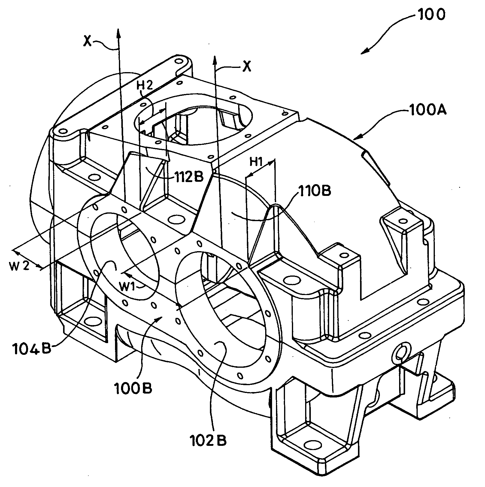
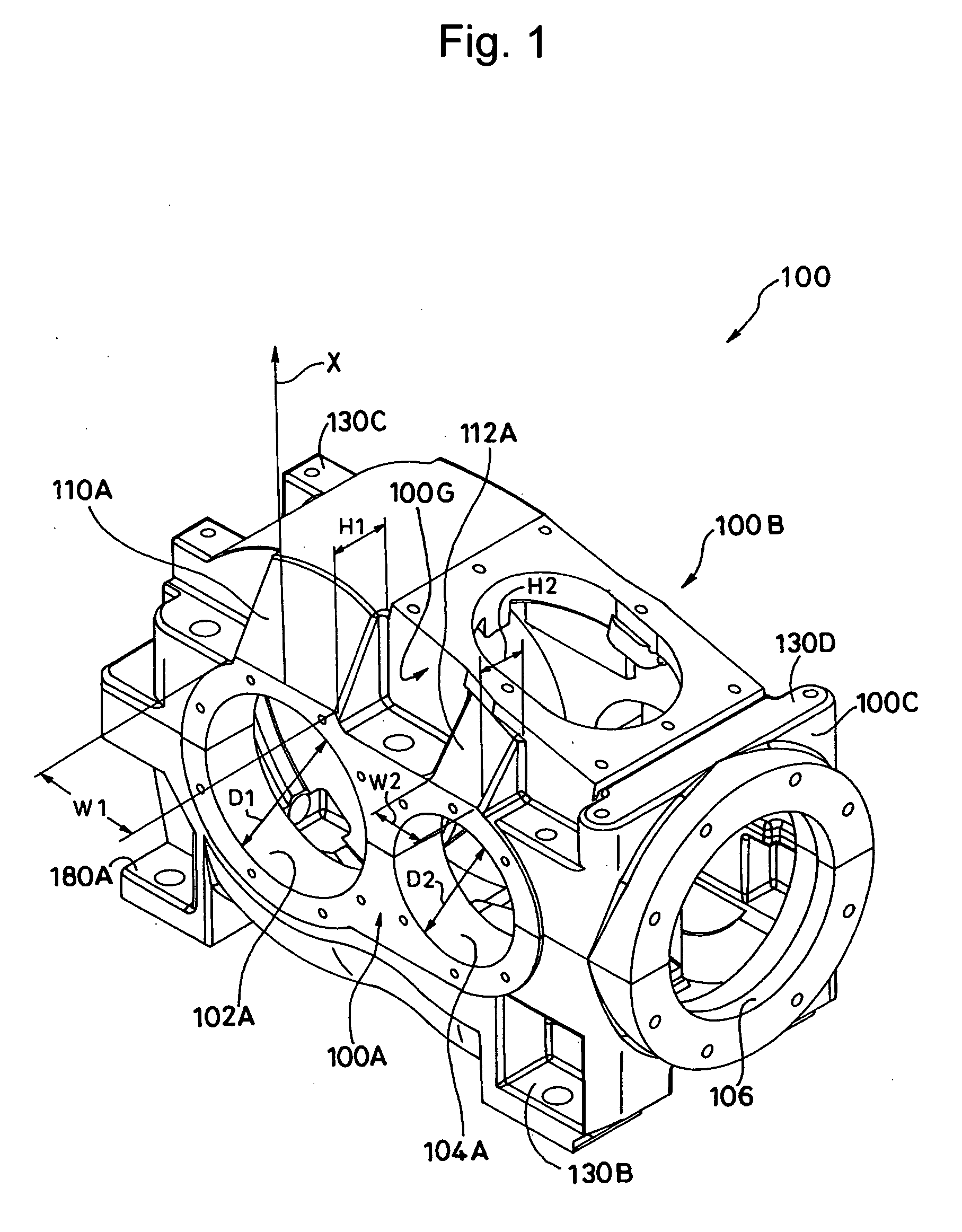
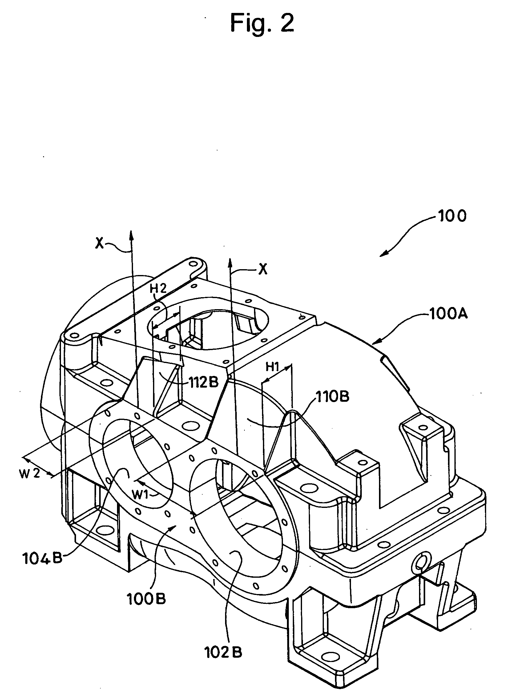
[0026]FIG. 1 is a perspective view of a gearbox 100 according to the exemplary embodiment of the present invention, with its front side viewed diagonally from above, FIG. 2 also being a perspective view thereof with its rear side viewed from above. FIG. 3 is a plan view illustrating the gearbox 100, FIG. 4 being a sectional view taken along the line IV-IV of FIG. 3, FIGS. 5 to 10 being a sectional view or a side view when taken along the lines V-V to X-X of FIG. 4, respectively.

[0027] As can be seen clearly from each figure, the gearbox 100 is symmetrical with respect to the centerline C. On a front side 100A and a rear side 100B of the gearbox 100, included are a first pair of shaft holes 102 (102A and 102B), into which an intermediate shaft (not shown) is to be inserted, and a second pair of shaft holes 104 (104A and 104B), into which...


PUM


Abstract

In a gearbox including three or more shaft holes, a vibration suppressor is formed with the gearbox and extends from at least one of shaft hole in a radial direction of the shaft hole. The vibration suppressor ensures a width which is greater than or equal to one fourth of the shaft hole diameter of the shaft hole, and a height that is greater than or equal to one sixth of the shaft hole diameter at a highest portion of the bivration suppressor.

Description

BACKGROUND OF THE INVENTION [0001] 1. Field of the Invention [0002] The present invention relates to a gearbox for use with a speed reducer or the like. [0003] 2. Description of the Related Art [0004] Various speed reducers have been conventionally used in power transmission systems for driving, industrial equipment in factories. In general, the speed reducer includes a gear transmission mechanism of a particular structure within a predetermined gearbox. In the gear transmission mechanism, the gears are meshed with each other, thereby periodic vibrations which depend on the number of teeth and the rotational speed are generated due to collision of tooth surfaces and slight deformation of the tooth surfaces, so that the so-called gear noise develops. Once the center frequency of the gear noise has become equivalent to the natural frequency of each member in the speed reducer, especially, that of the gearbox, or to an integral multiple of the natural frequency thereof, the noise might...

Claims


Application Information

Patent Timeline
IPC IPC(8): F16H57/02F16F15/02F16H57/028F16H57/029F16H57/03
CPCF16H57/0006F16H57/028Y10T464/50Y10T74/2186F16H2057/02073F16F15/10
Inventor YAMASAKI, YASUMASAYOSHIMURA, TAKUYA
Owner SUMITOMO HEAVY IND LTD
Why Eureka
Try Eureka