Fluid cutting device and method of use

Inactive Publication Date: 2006-07-20
DEPUY MITEK INC
View PDF21 Cites 62 Cited by
  • Summary
  • Abstract
  • Description
  • Claims
  • Application Information

AI Technical Summary

Benefits of technology

[0008] Disclosed herein are fluid cutting jet control systems that provide improved cutting performance. In one aspect, the control system achieves improved performance by controlling the jet power

Problems solved by technology

Conventional cutting systems often lack robust controllers that can account for variations within the fluid cutting jet system.
Such controllers might only limit the maximum pressure in the interest of safety.
However, this system fails to account for the use of different surgical cutting wands and/or orifice di

Method used


Image

  • Fluid cutting device and method of use
  • Fluid cutting device and method of use
  • Fluid cutting device and method of use

Examples


Embodiment Construction

[0021] Disclosed herein is a fluid jet cutting control system that provides improved cutting performance. The system includes a pump which delivers a fluid stream to an end effector. The fluid exits the end effector as a cutting stream that can be used to create surgical incisions. In one aspect, improved system performance is achieved by controlling the jet power of the cutting stream. In a further aspect, pump power is manipulated to control the jet power of the cutting stream.

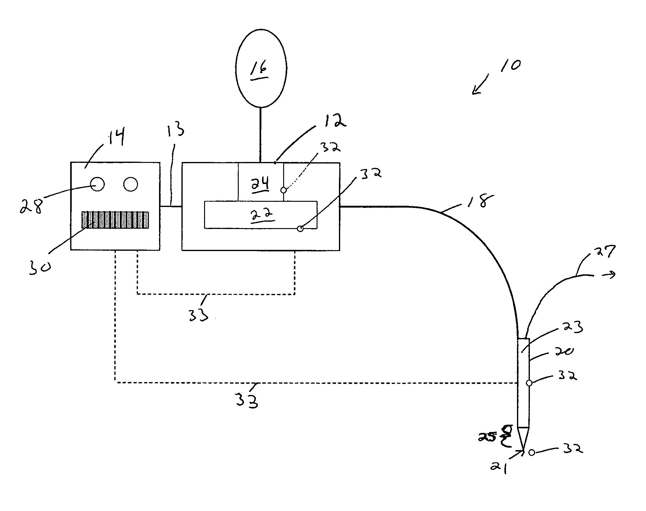
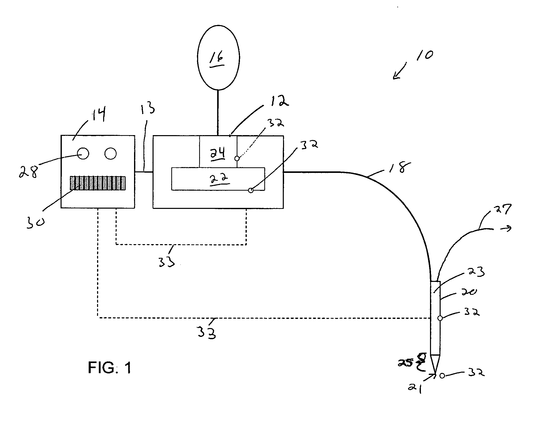
[0022]FIG. 1 illustrates an exemplary fluid cutting jet system 10, including a pump 12 that receives fluid from fluid source 16 and delivers the fluid, via a delivery tube 18, to an end effector 20. When the fluid is pressurized by pump 12, it traverses end effector 20 and passes through an orifice 21. Console 14 allows a user to vary the intensity of the fluid stream leaving orifice 21. For example, console 14 allows a surgeon to control the cutting speed of the fluid cutting jet.

[0023] Pump 12 can includ...


PUM

PropertyMeasurementUnit
Pressureaaaaaaaaaa
Poweraaaaaaaaaa
Flow rateaaaaaaaaaa

Abstract

A fluid jet cutting system that provides more consistent cutting jet performance is disclosed. The system includes a fluid pump for pressurizing fluid having a fluid inlet and a fluid outlet. The pump delivers pressurized fluid to a delivery tube that is in fluid communication with an end effector. The end effector includes an orifice for delivering pressurized fluid to tissue. The power delivered to the pump is controlled to produce a desired fluid cutting jet.

Description

CROSS-REFERENCE TO RELATED APPLICATIONS [0001] Not applicable. STATEMENT REGARDING FEDERALLY SPONSORED RESEARCH [0002] Not Applicable. BACKGROUND OF THE INVENTION [0003] High pressure fluid streams provide one method of cutting tissue during a surgical procedure. Such “fluid jet cutting” has been used to cut, drill, bore, perforate, strip, delaminate, liquefy, ablate, and / or shape a diverse range of tissues. For example, fluid jets have been used to disintegrate and shape eye lens tissue, remove deposits from a vein or artery, and remove or shape meniscal tissue. [0004] In use, a fluid is pressurized and a thin cutting beam is formed as the fluid stream travels through a tiny jet orifice in a surgical hand piece. A surgeon can vary the fluid pressure and / or the surgical hand piece depending on the type of surgical procedure that is performed. For example, selective variation of the jet stream pressure, (e.g., between 1 and 50,000 p.s.i.), allows the surgeon to cut hard bone, soft bo...

Claims


Application Information

Patent Timeline
IPC IPC(8): B26D1/00
CPCA61B17/3203A61B2017/00022A61B2017/00199Y10T83/04
Inventor MCRURY, IAN D.SENGUN, MEHMET Z.WEINERT, CHRISTOPHER
Owner DEPUY MITEK INC
Why Eureka
Try Eureka