Centralizer-based survey and navigation device and method

a navigation device and centralizer technology, applied in the field of centralizer-based survey and navigation device and method, can solve the problems of inability to provide a high degree of accuracy for systems based on inclinometers, accelerometers, gyroscopes, etc., and achieve the effect of reducing the number of devices and measuring the size of the survey and reducing the difficulty of surveying

Active Publication Date: 2006-07-20
RAYTHEON CO
View PDF11 Cites 27 Cited by
  • Summary
  • Abstract
  • Description
  • Claims
  • Application Information

AI Technical Summary

Benefits of technology

[0016] Another exemplary embodiment relates to a compensator for zero drift of detectors measuring orientation of the sensor string and detectors measuring relative displacement of the centralizers by inducing rotation in the sensor string or taking advantage of rotation of a drill string. If the detector measuring orientation of the sensor string is an accelerometer, such a device can calculate the zero drift of the accelerometer detector by enforcing that the average of the detector-measured value of local Earth's gravity to be equal to the known value of g at a given time, and / or where the zero drift of detectors measuring relative displacement of the centralizers is compensated for by enforcing that the readings of the strain gauges follow the same angular dependence on the rotation of the string as the angular dependence measured by inclinometers, accelerometers, and or gyroscopes placed on the drill string or sensor string that measure orientation of the sensor string with respect to the Earth's gravity.

Problems solved by technology

One problem facing all of these systems is that they tend to be too large to allow for a “measurement while drilling” for small diameter holes.
Systems based on inclinometers, accelerometers, gyroscopes, and / or magnetometers are also incapable of providing a high degree of accuracy because they are all influenced by signal drift, vibrations, or magnetic or gravitational anomalies.
In addition to being depth limited, such systems are also deficient in that they require a worker to carry a receiver and walk the surface over the drilling head to detect the emissions and track the drilling head location.
Such systems cannot be used where there is no worker access to the surface over the drilling head or the ground is not sufficiently transparent to the emissions.

Method used


Image

  • Centralizer-based survey and navigation device and method
  • Centralizer-based survey and navigation device and method
  • Centralizer-based survey and navigation device and method

Examples


Embodiment Construction

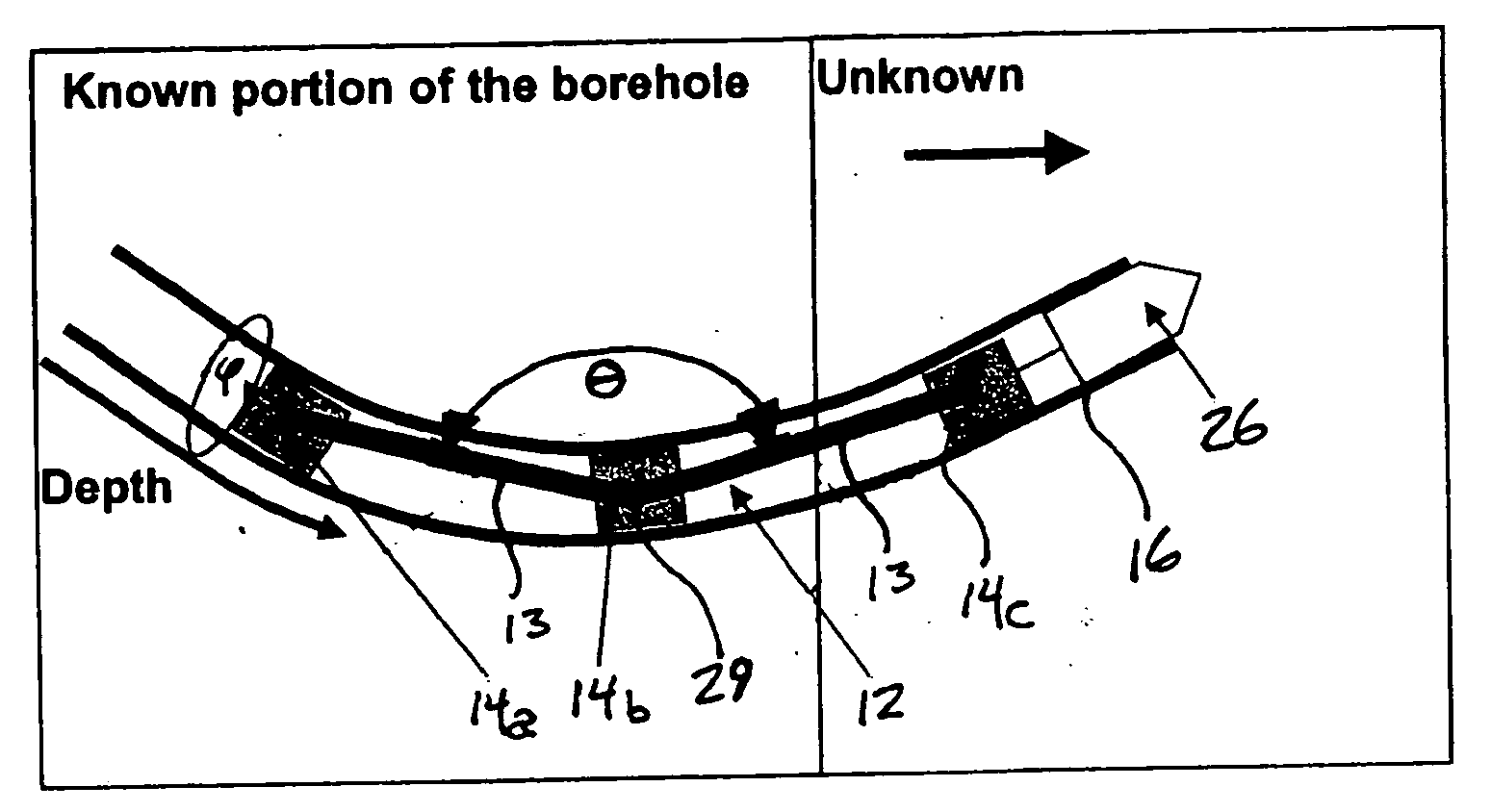
[0038] The invention relates to a Centralizer-based Survey and Navigation (hereinafter “CSN”) device, system, and methods, designed to provide passageway and down-hole position information. The CSN device can be scaled for use in passageways and holes of almost any size and is suitable for survey of or navigation in drilled holes, piping, plumbing, municipal systems, and virtually any other hole environment. Herein, the terms passageway and borehole are used interchangeably.

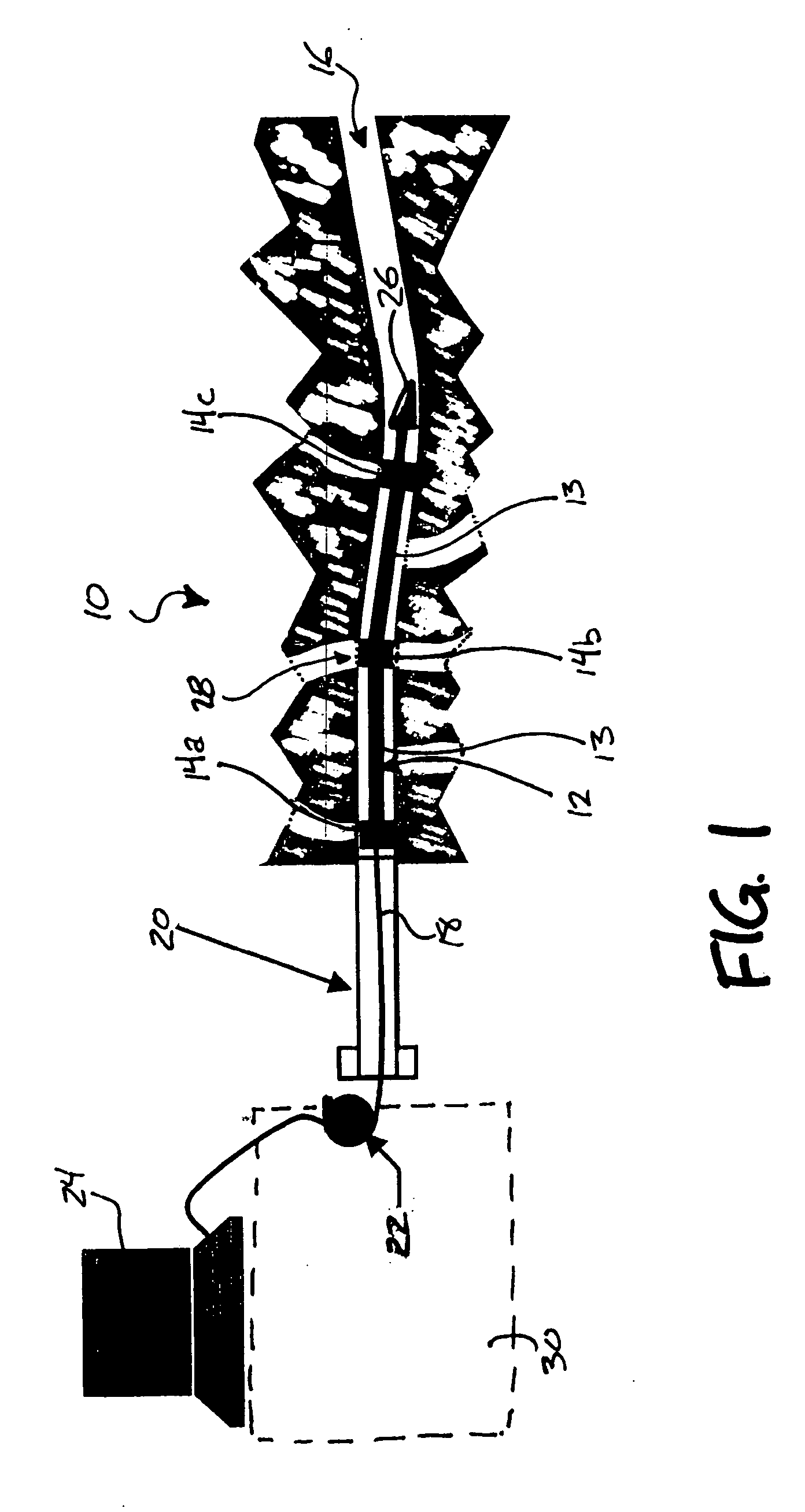
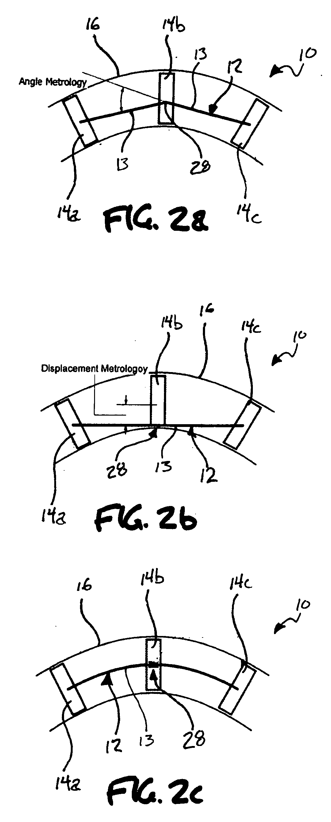
[0039]FIG. 1 shows the basic elements of a directional drilling system incorporating a CSN device 10, a sensor string 12 including segments 13 and centralizers 14 (14a, 14b, and 14c), a drill string 18, an initializer 20, an odometer 22, a computer 24, and a drill head 26. A metrology sensor 28 is included and can be associated with the middle centralizer 14b, or located on the drill string 18. The odometer 22 and computer 24 hosting a navigation algorithm are, typically, installed on a drill rig 30 and in commu...


PUM


Abstract

A Centralizer based Survey and Navigation (CSN) device designed to provide borehole or passageway position information. The CSN device can include one or more displacement sensors, centralizers, an odometry sensor, a borehole initialization system, and navigation algorithm implementing processor(s). Also, methods of using the CSN device for in-hole survey and navigation.

Description

[0001] This application claims priority to U.S. Provisional Application Ser. No. 60 / 635,477, filed Dec. 14, 2004, the entirety of which is incorporated by reference herein.FIELD OF THE INVENTION [0002] The present invention relates, but is not limited, to a method and apparatus for accurately determining in three dimensions information on the location of an object in a passageway and / or the path taken by a passageway, e.g., a borehole or tube. BACKGROUND OF THE INVENTION [0003] The drilling industry has recognized the desirability of having a position determining system that can be used to guide a drilling head to a predestined target location. There is a continuing need for a position determining system that can provide accurate position information on the path of a borehole and / or the location of a drilling head at any given time as the drill pipe advances. Ideally, the position determining system would be small enough to fit into a drill pipe so as to present minimal restriction ...

Claims


Application Information

Patent Timeline
Patent Type & Authority Applications(United States)
IPC IPC(8): E21B47/02
CPCE21B17/1057E21B47/022
Inventor DOLGIN, BENJAMINSULIGA, WILLIAMGOLDSTEIN, BRETTVICKERMAN, DAVIDHILL, JOHN L. IIISHENHAR, JORAMGRINDSTAFF, KEITHCOTTEN, STEVEN A.
Owner RAYTHEON CO
Why Eureka
Try Eureka