
Display rod lock mechanism

a technology of lock mechanism and display rod, which is applied in the direction of building locks, show hangers, constructions, etc., can solve the problems of reducing the amount of sales, increasing the difficulty of a shoplifter from quickly removing a large number, and difficult to apprehend, so as to prevent the rapid removal of a large number and high effectiveness

Inactive Publication Date: 2006-07-20
INVUE SECURITY PROD INC
View PDF74 Cites 92 Cited by
  • Summary
  • Abstract
  • Description
  • Claims
  • Application Information

AI Technical Summary

Benefits of technology

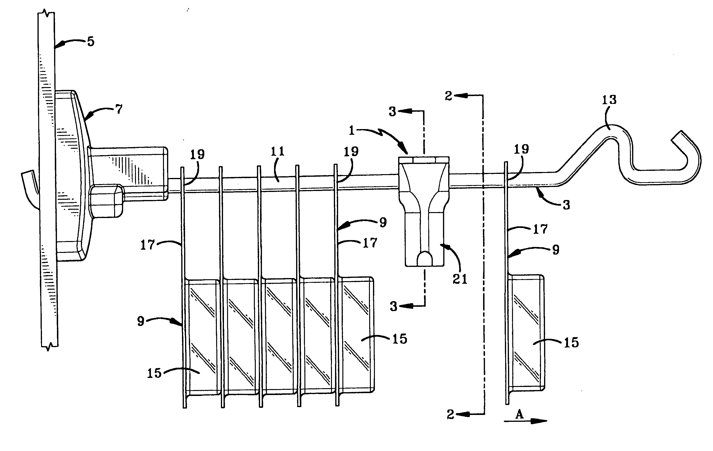
[0009] The present invention provides the security device for display racks that prevents the rapid removal of a large number of the displayed items of merchandise from display rods extending outwardly from the rack by placing a simple, compact, yet highly effective locking device on a linear length of the display rod located between a number of the items stored thereon. This will enable those items located between the security device and the distal end of the display rod to be removed by a customer yet prevents any removal of those items between the display rack and locking device until a clerk unlocks the security device and repositions it behind a number of the already stored items, or places new items inbetween the security device and distal end of the rod for subsequent removal by the customer.
[0010] Another aspect of the present invention is to provide the display rod security device as a simple two-piece component pivotally joined at one end, each of which has a semicircular slot formed therein, which when in a closed locked position forms a circular opening through which the display rod extends, and which has a sufficient linear length or configuration to prevent it from being removed from a bent end of the display rod.
[0012] Another feature of the present invention is to form the locking plunger of a magnetically attractable material whereby a magnetic key when placed at a specific location on the lock mechanism will move the plunger to the unlocked position enabling the security device to be easily pivoted to an open position for removal of the device from the rack and subsequent reattachment thereto.
[0013] A further aspect of the present invention is to form the two half body members inexpensively of rigid plastic material which is strong enough to prevent a thief from easily prying the two lock body members apart, and which can be constructed of a minimum number of component parts thereby enabling the lock mechanism to be mass produced relatively inexpensive encouraging the use thereof by merchants to reduce shoplifting.

Problems solved by technology

Unfortunately, such merchandise is an easy target for shoplifters and it has been found that shoplifters can rapidly empty all of the merchandise from a pegboard display rod and make off with merchandise without being detected, or even if detected upon passing through a checkout security gate, will be difficult to apprehend.
This has the disadvantage in that it requires the customer to contact a clerk who must unlock the lock mechanism from the end of the rod to enable the customer to remove the merchandise for purchase.
It has been found that this reduces the amount of sales since many customers do not wish to wait or take the time to find a clerk to unlock the security device to enable the customer to secure the desired item.
This has proven satisfactory to some extent in that it increases the difficulty of a shoplifter from rapidly removing a large number of the items from the storage rack.
However, it does not prevent the shoplifter from removing all of the items of merchandise from the rod if the shoplifter uses a large amount of force upon sweeping the items from the rod or bunches the items together enabling a plurality of the items to be removed in one motion from the rod.

Method used


Image

  • Display rod lock mechanism
  • Display rod lock mechanism
  • Display rod lock mechanism

Examples


Embodiment Construction

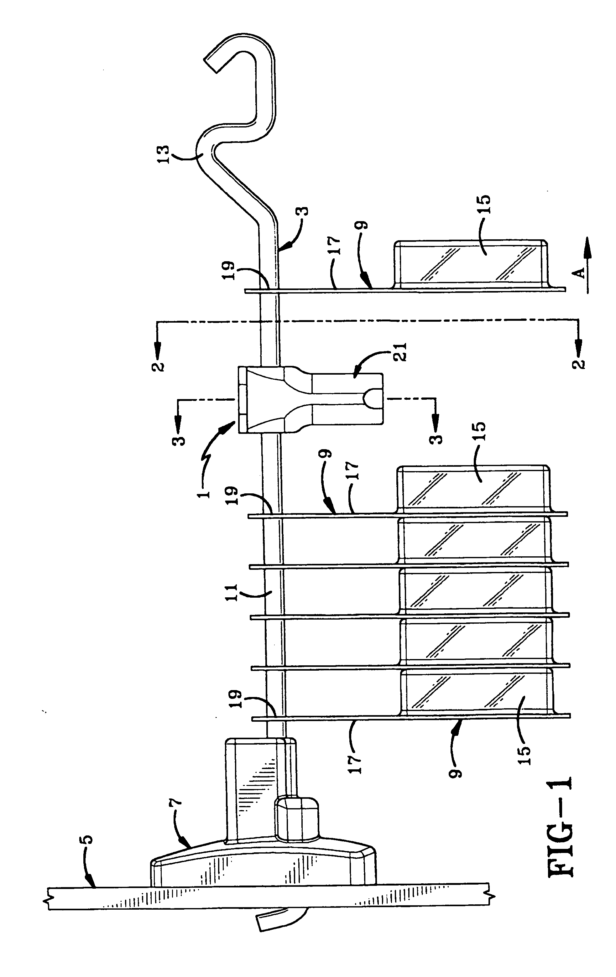
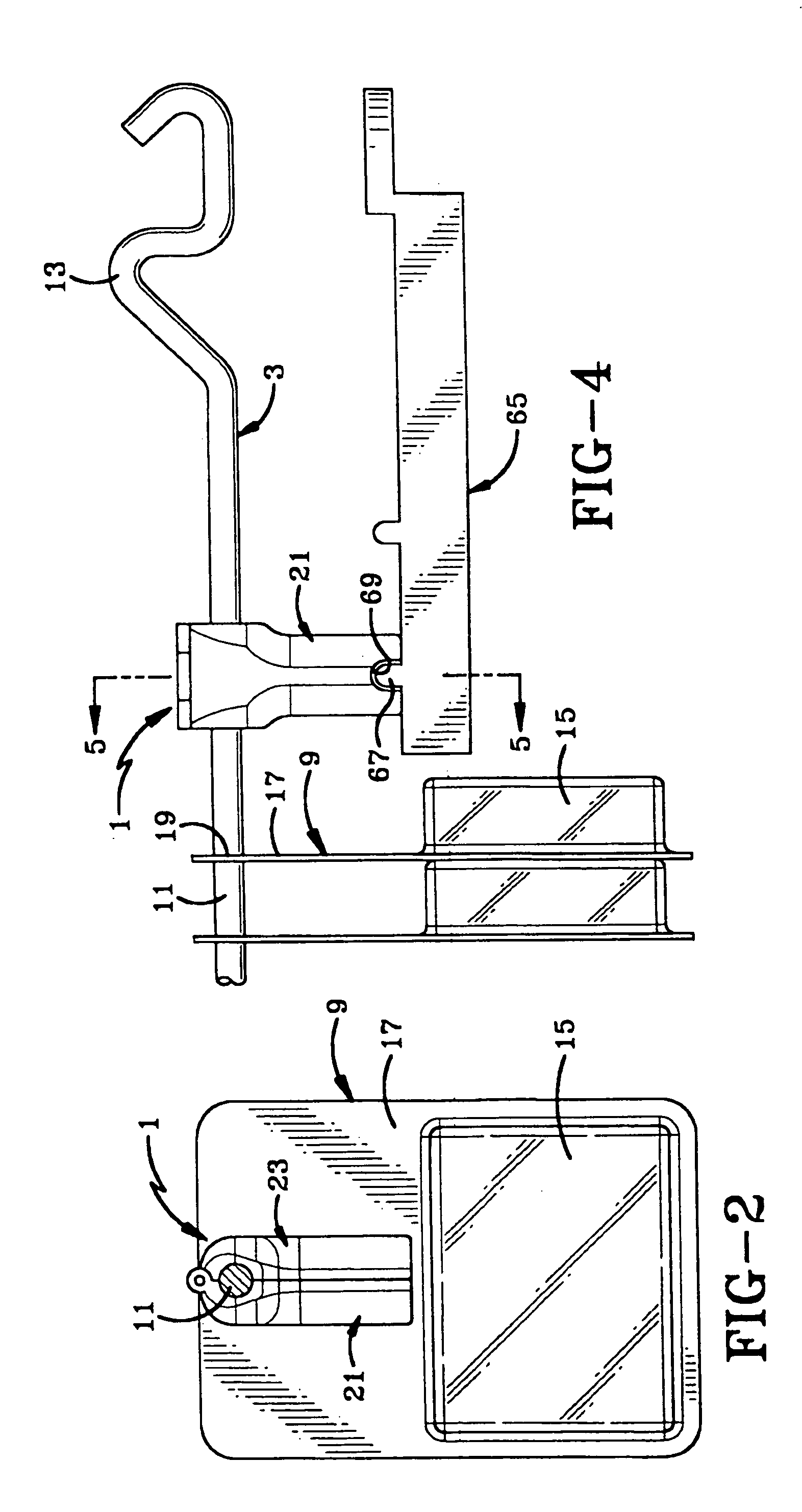
[0025] The display rod lock mechanism of the present invention is indicated generally at 1, and is shown in FIG. 1 mounted on a merchandise display rod 3 which extends outwardly in a cantilevered-like fashion from a support surface 5 and is attached thereto by various types of attachment mechanisms 7. Attachment 7 is preferably some type of secure device which when attached to support 5 prevents removal of the rod therefrom without considerable manipulation or without sounding an alarm to prevent a shoplifter from completely removing rod 3 including all of the various items of merchandise indicated at 9, suspended therefrom. Rod 3 preferably is formed of a rigid round metal member having a generally straight elongated linear section 11 which terminates in a curved distal end 13. The items of merchandise 9 can be blister packs 15 or other type of containers in which certain merchandise is stored. The packs are suspended from rod 3 by a flat card-like section 17 having a hole 19 forme...


PUM


Abstract

A lock mechanism is mounted on a merchandise display rod to prevent the removal of some items of merchandise from the rod. A pair of members are pivotally joined at one end and move between locked and unlocked positions. Each of the members is formed with a partial slot which align with each other when in the locked position to extend about the rod. A magnetically attractable plunger is mounted within one of the members and engages a recess formed in the other member to secure the members in a closed locked position on the rod. A magnetic key moves the plunger to an unlocked position to enable the members to pivot apart to an unlocked open position. The distal end of the rod is bent at an angle sufficient to prevent sliding removal of the lock mechanism from the rod when the members are in the locked position yet enable removal of merchandise items forward of the lock mechanism from the rod.

Description

CROSS REFERENCE TO RELATED APPLICATIONS [0001] This application claims priority from U.S. provisional application serial No. 60 / 644,207 filed Jan. 14, 2005; the disclosure of which is incorporated herein by reference.BACKGROUND OF THE INVENTION [0002] 1. Technical Field [0003] The present invention relates to security devices, and particularly to a security device that prevents large numbers of items of merchandise from being rapidly removed from display racks, and in particular from display rods. Specifically, the present invention relates to the security device that is easily attached and locked on the display rod which allows one or several items of merchandise to be removed from the rack at any one time, but protects a number of the items from being removed from the rack by a shoplifter. [0004] 2. Background Information [0005] Numerous items of merchandise are displayed for sale on long protruding rods that are supported from a piece of pegboard, slat board, or other type of sup...

Claims


Application Information

Patent Timeline
IPC IPC(8): A47F5/08
CPCA47F5/0861
Inventor NAGELSKI, KEITH C.MARSILIO, RONALD M.
Owner INVUE SECURITY PROD INC
Learn More