
Hybrid laser processing method and hybrid laser torch used in the method

a laser processing method and hybrid technology, applied in metal-working equipment, welding equipment, manufacturing tools, etc., can solve the problems of increasing penetration and acceleration of processing speed, and achieve the effects of reducing glare, easy and correct visual recognition of processed surfaces, and easy adjustmen

Inactive Publication Date: 2006-07-20
PANASONIC CORP
View PDF4 Cites 26 Cited by
  • Summary
  • Abstract
  • Description
  • Claims
  • Application Information

AI Technical Summary

Benefits of technology

[0010] With this method, the first and second laser beams from two different laser systems are superposed and irradiated as a hybrid laser beam on the workpiece, wherein the two laser beams respectively have large and small spot sizes D1 and D2, whereby the center of the laser beam spot is processed faster than the surrounding area, which accelerates the processing and increases penetration. In a preferred embodiment, while the first laser beam with high power output achieves necessary processing width and strength, the second laser beam, which is with lower output than the first laser beam, is focused in the smaller effective spot size D2 than D1 to concentrate laser energy to a specific area. Therefore, while the first laser beam covers the entire processing width, the second laser beam increases the processing speed and depth in a more limited area, as compared to the case where both laser beams have the same focus diameter. As a result, even a metal material having high reflectivity such as aluminum is processed with a sufficient weld width, or penetration width, and penetration depth, and at high speed. Also, the processing of the specific area with accelerated speed and increased penetration using the hybrid laser beam effectively suppresses generation of sputtered particles.
[0032] The first and second sensing parts may further be covered by a hood to prevent adverse effects of ambient light and dust around the hybrid laser torch.

Problems solved by technology

This way, a keyhole is formed in the spot center, which grows in depth and further accelerates the processing speed and increases penetration.

Method used


Image

  • Hybrid laser processing method and hybrid laser torch used in the method
  • Hybrid laser processing method and hybrid laser torch used in the method
  • Hybrid laser processing method and hybrid laser torch used in the method

Examples


Embodiment Construction

[0050] Preferred embodiments of the hybrid laser processing method and hybrid laser torch used in the method of the present invention will be hereinafter described in detail with reference to the drawings for a better understanding of the invention. It should be understood that the description of the following specific examples is given for purposes of illustration only and not intended to limit the scope of the claims.

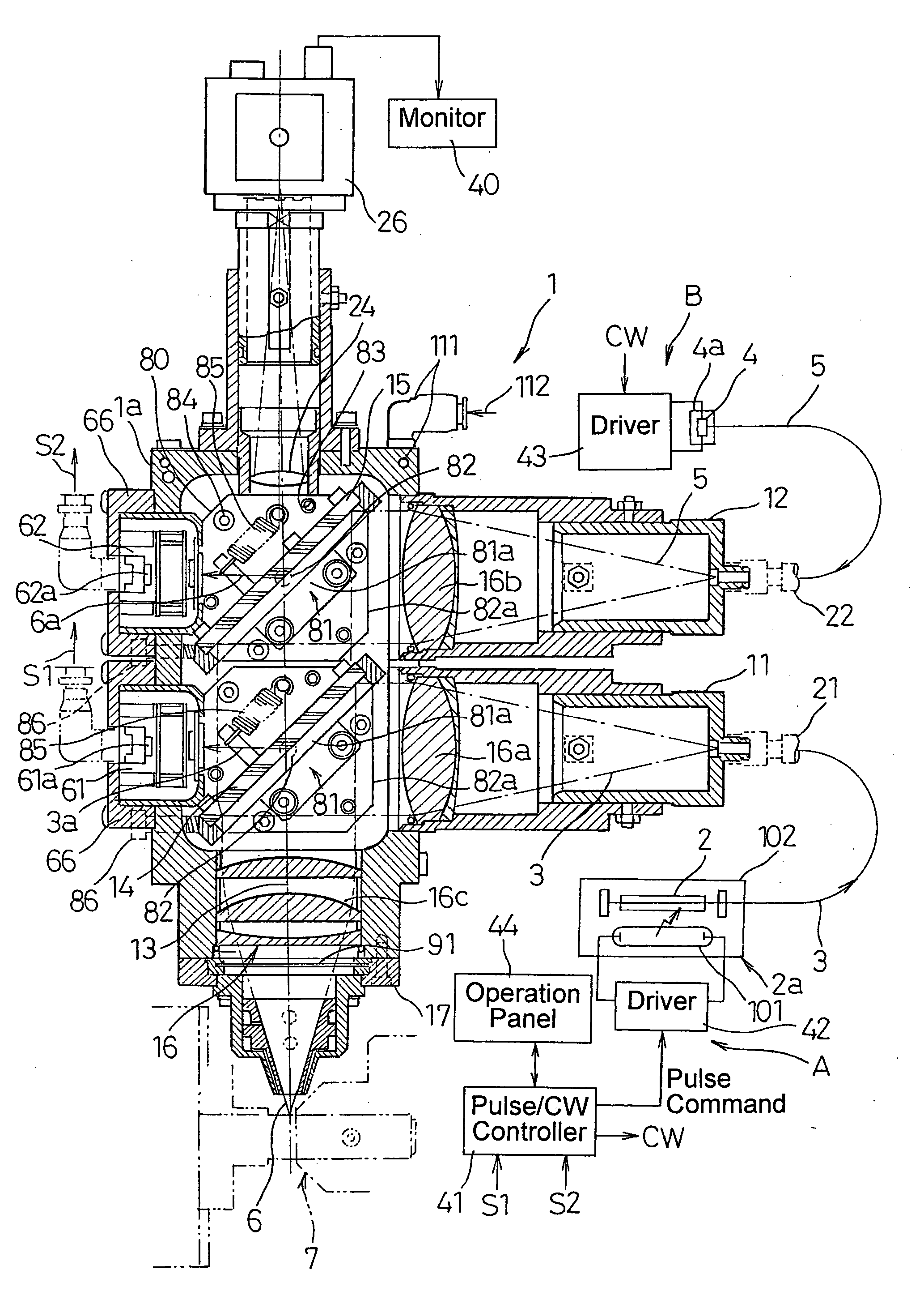
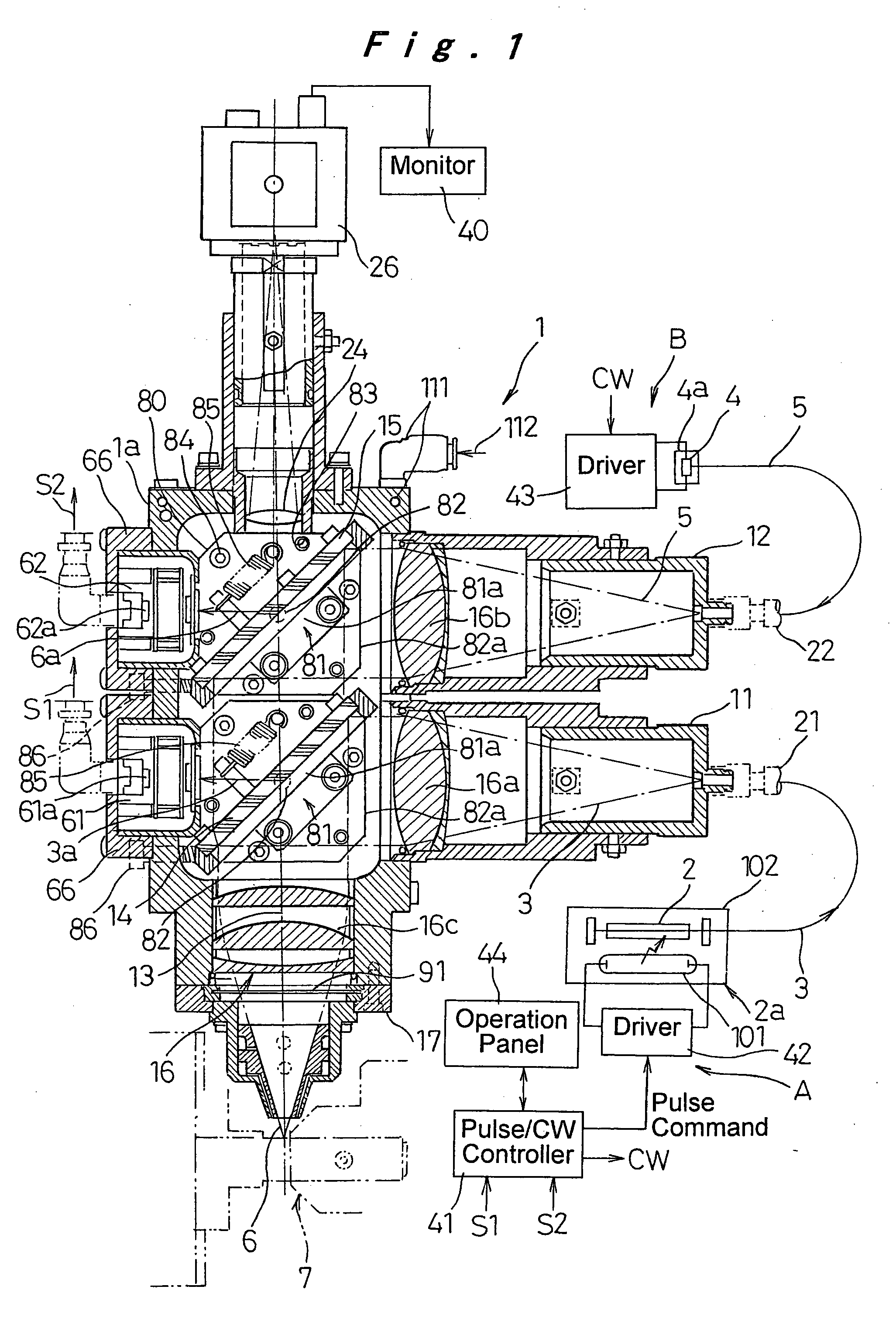
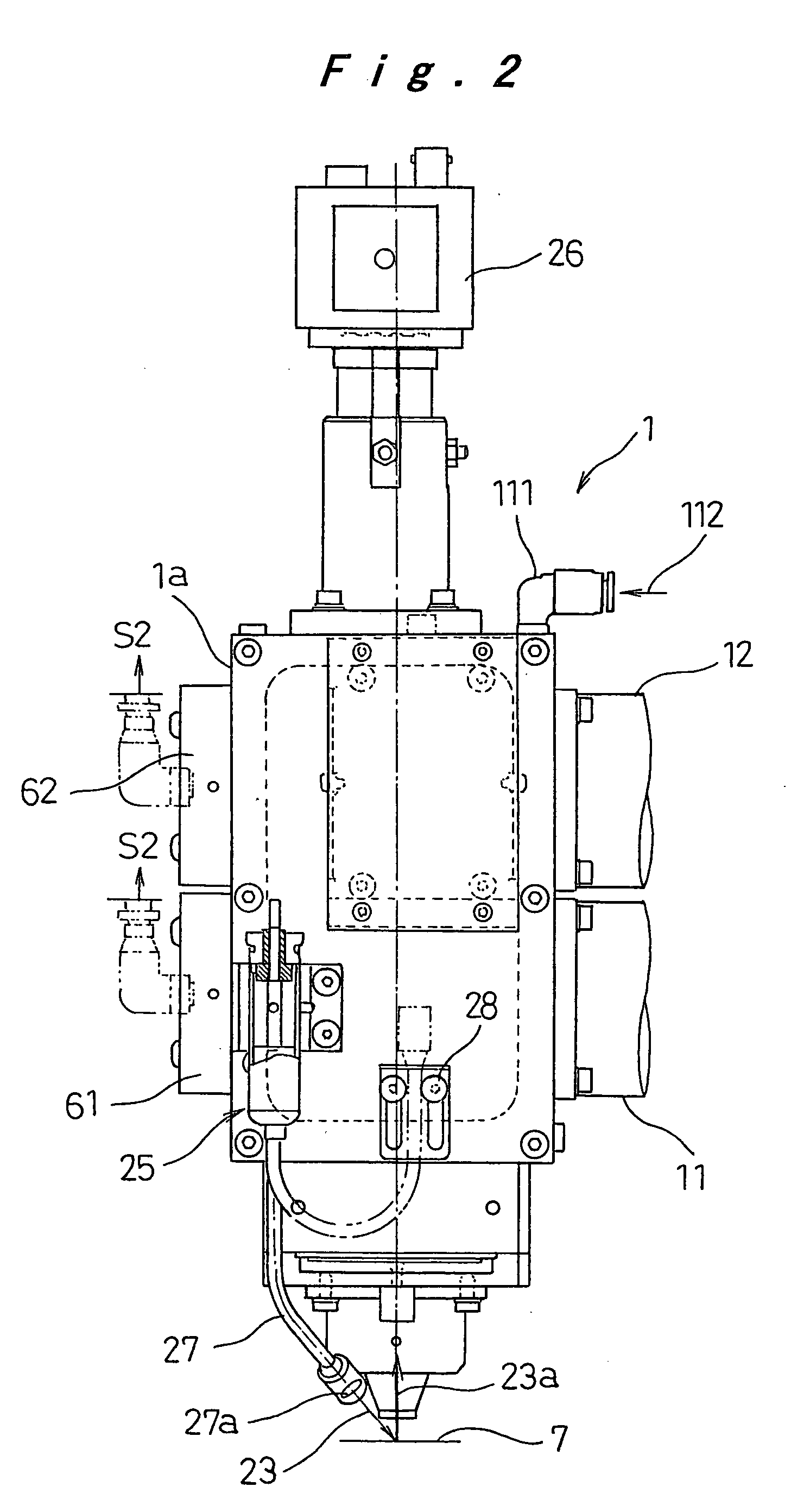
[0051] Referring to FIG. 1 which illustrates a hybrid laser torch 1 used in one embodiment of the hybrid laser processing method, first and second laser beams 3 and 5 from two different laser systems A and B are emitted as a hybrid laser beam 6 to a workpiece 7 for the processing. As shown in FIG. 3, the focus diameter, or the effective spot size D2, of the second laser beam 5 on the workpiece 7 is smaller than the effective spot size D1 of the first laser beam 3. The “effective spot size” here means the size of the laser beam 3 or 5 that is effectively emitted on th...


PUM

PropertyMeasurementUnit
Poweraaaaaaaaaa
Diameteraaaaaaaaaa
Sizeaaaaaaaaaa

Abstract

First and second laser beams from two different laser systems are superposed and irradiated as a hybrid laser beam on a workpiece. The effective spot size of second laser beam on the workpiece is smaller than that of the first laser beam. Thereby, a workpiece of a metal material having high reflectivity is processed with a sufficient weld penetration depth and width, and at high speed.

Description

BACKGROUND OF THE INVENTION [0001] 1. Field of the Invention [0002] The present invention relates to a hybrid laser processing method and a hybrid laser torch used in the method, wherein a workpiece is processed with a hybrid laser beam using laser beams from two different laser systems, i.e., a solid-state laser medium such as YAG and a semiconductor laser (LD). [0003] 2. Description of the Related Art [0004] Japanese Patent Publication No. 2000-005892 shows a laser welding method, wherein a laser beam is focused at a plurality of positions along the optical axis to achieve a desired weld penetration depth and weld width. Japanese Patent Publication No. 2002-028795 shows a method wherein two YAG laser beams are superposed so that a metal material having high reflectivity and high heat dissipation rate can be processed with a sufficient cross section and depth of weld penetration. Japanese Patent Publication No. 2003-164983 shows a method wherein a laser beam is used together with a...

Claims


Application Information

Patent Timeline
IPC IPC(8): B23K26/067
CPCB23K26/0604B23K26/0613B23K26/21
Inventor SAKURAI, TSUTOMUTOYA, KAZUHIROFUNAMI, KOJI
Owner PANASONIC CORP
Learn More