Hot reduced coil tubing

a technology of coiling and metallic tubing, which is applied in the direction of metal-working equipment, welding equipment, manufacturing tools, etc., can solve the problems of shortening the production time of ct, and achieve the effects of improving the quality, reliability and resistance of coiling, improving the speed and efficiency of ct manufacturing, and widening the width

Inactive Publication Date: 2006-07-20
DUBOIS JON D
View PDF27 Cites 37 Cited by
  • Summary
  • Abstract
  • Description
  • Claims
  • Application Information

AI Technical Summary

Benefits of technology

[0013] The present invention undertakes to further improve the quality, reliability, and resistance to coiling and uncoiling stresses of relatively long lengths of CT and to improve the speed and efficiency of the manufacture of CT. The present invention utilizes widths of feed stock that are deliberately selected to be in excess of the circumference, and hence the OD, of CT produced according to the prior art. The present invention may utilize thicknesses of feed stock that are deliberately selected to be in excess of the wall thickness of the CT produced in accordance with the prior art. In the manufacturing process of CT according to the present invention, master coils may be slit into strips having wider widths and/or greater thicknesses than in the prior art. This results in less waste of the steel from the master coil and further facilitates the use of the end cuts to produce higher quality CT. In addition, because the wall thickness of the CT manufactured in accordance with the present invention is not required to correspond substantially identically to the thickness of the master coil or strips cut from the master coil, fewer thicknesses of flat stock are needed to manufacture a full range of wall thicknesses in the CT. In the manufact

Problems solved by technology

This results in shorter productio

Method used


Image

  • Hot reduced coil tubing
  • Hot reduced coil tubing
  • Hot reduced coil tubing

Examples


Embodiment Construction

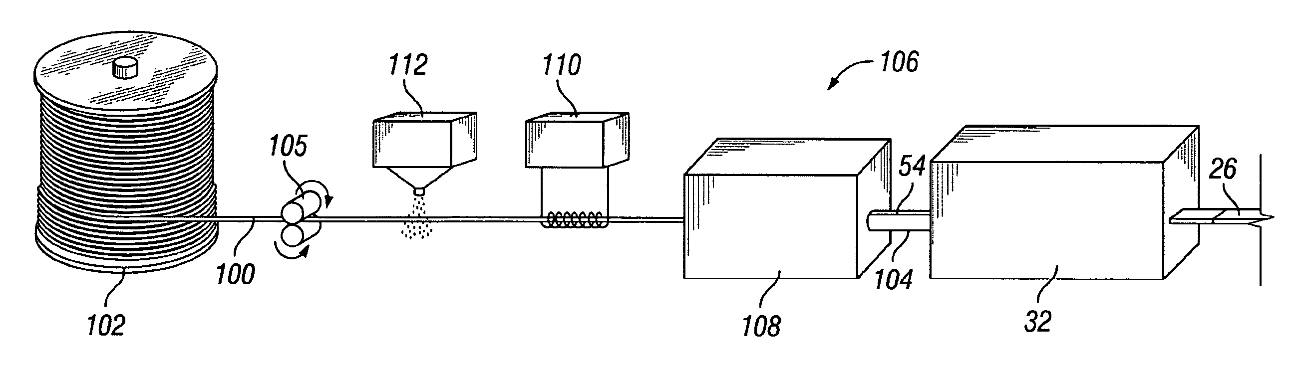
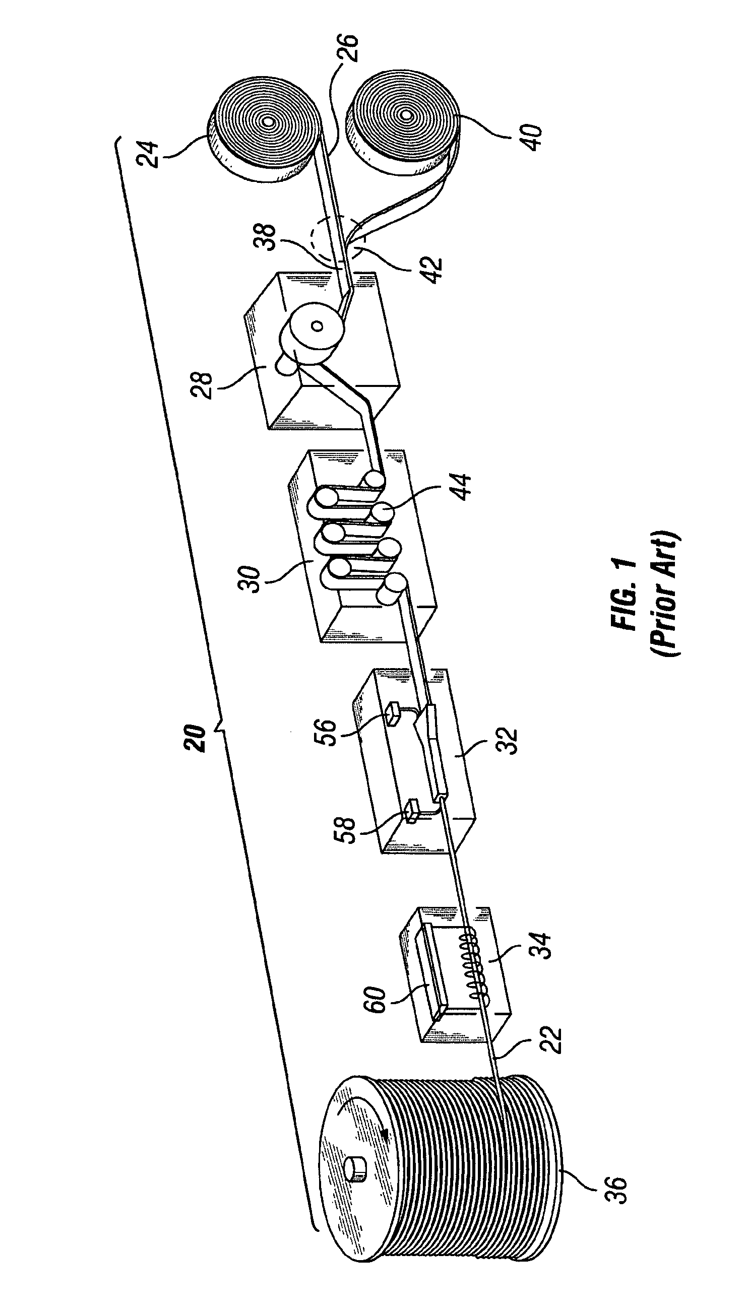
[0035] In the prior art system 20 as depicted in FIG. 1, a length of CT 22 could be made by the following process. A first feed coil 24 of flat strip stock 26 is fed to an accumulator 28, then through a conditioner 30 to remove some of the coiling stresses and help flatten the flat strip stock 26. Then the strip stock 26 is fed into a tube mill or tube former 32 following which the tubing is heat treated in a heat treater 34 and, following cooling, is spooled onto a takeup reel 36. The first feed coil 24 of flat stock 26 is fed through the system 20 until the trailing end 38 of the first feed coil 24 is reached. Thereafter, a second feed coil 40 is welded to the first feed coil 24 by means of a bias weld joint 42, and the process continues without interruption until a desired length of CT 22 has been spooled onto the takeup reel 36. The accumulator 28 is positioned so that the tube mill 32 continues to function and tubing made from the leading end and center section of the first fee...


PUM

PropertyMeasurementUnit
Angleaaaaaaaaaa
Lengthaaaaaaaaaa
Thicknessaaaaaaaaaa

Abstract

Continuous coil tubing made from shorter lengths of flat metal strip which are spliced end-to-end and formed into tubular form and seam welded and thereafter introduced into a forging or hot reduction process. Finished coil tubing is withdrawn from the process at a different rate than flat metal strip is fed into the process. Welds made to the flat metal strip blend into and substantially disappear from the finished coil tubing.

Description

RELATED APPLICATION [0001] There are no related applications. BACKGROUND OF THE INVENTION [0002] I. Field of the Invention [0003] This invention relates generally to oilfield coilable metallic tubing for use in wellbores, tubular strings, pipelines, bores, boreholes, and other oilfield applications. [0004] II. Description of Related Art [0005] Coil tubing (“CT”) is typically a relatively long continuous length of tubing that can be run in and out of a wellbore, tubular string, pipeline, bore and boreholes. CT is widely used in the oil and gas industry for drilling, completion, production, and workover operations. In addition, CT may be used for control lines, umbilicals, and in other applications requiring relatively long and durable tubing. CT is commonly manufactured from steel or steel alloy. Accessories or tools may be affixed interior to, exterior to, or at the end of, a length of CT to assist in its use or enhance its utility. Such tools and accessories include nozzles, sensor...

Claims


Application Information

Patent Timeline
IPC IPC(8): B23K31/02B21D39/00
CPCB21C37/08B21C37/0807B21C37/0811
Inventor DUBOIS, JON DAVID
Owner DUBOIS JON D
Why Eureka
Try Eureka