Control of coolant flow rate for vehicle heating

a technology for vehicle heating and coolant flow rate, which is applied in the direction of space heating and ventilation control system, heating types, lighting and heating apparatus, etc. it can solve the problem of low coolant flow rate, and heater core not being able to heat the air being directed into the cabin sufficiently for the occupants to feel comfortabl

Active Publication Date: 2006-07-20
NISSAN MOTOR CO LTD
View PDF10 Cites 33 Cited by
  • Summary
  • Abstract
  • Description
  • Claims
  • Application Information

AI Technical Summary

Benefits of technology

[0012] In another embodiment of the invention, there is a coolant flow device, comprising, an electronic processor and a memory, wherein the memory stores a value of a predetermined temperature difference and at least one algorithm based on an equation to automatically determine the temperature of air exiting a heater core, the equation being based on variables including, a temperature of air exiting the heater core, a temperature of coolant at the inlet of the heater core, a temperature of air prior to entering the heater core, a variable ratio of coolant enthalpy per degree and heater core enthalpy per degree, and a variable heater core performance parameter based on Cc / Ch, wherein the electronic processor is adapted to automatically determine the temperature of air leaving the heater core utilizing the algorithm, automatically determine a temperature difference between the temperature of coolant at a first flow rate before the coolant enters the heater core, and automatically issue a command to increase the flow rate of the coolant to a second flow rate higher than the first flow rate if the temperature difference is greater than the stored value of the predetermined temperature difference.

Problems solved by technology

This is sometimes a problem, because by controlling the flow rate of coolant through the heater core solely based on engine parameters, the true need to achieve a minimum circulation rate through the heater core, which may be needed to ensure that the climate control system can provide hot air at an adequate temperature and at an adequate mass flow rate to the cabin, is ignored.
This is especially the case in situations of extremely cold ambient weather at low engine speeds and / or low coolant pump speeds (and thus low coolant flow rates).
Thus, low coolant flow rate may be a problem because, depending on the ambient temperatures and / or the increase in room temperature that the cabin occupants desire, the heater core may not be able to heat the air being directed into the cabin sufficiently for the occupants to feel comfortable.
However, this may result in a reduction in fuel efficiency as well as increased wear and tear on automobile components (e.g., a water pump that now must run twice as fast), thus making the automobile less economical, less environmentally friendly and more maintenance intensive.

Method used


Image

  • Control of coolant flow rate for vehicle heating
  • Control of coolant flow rate for vehicle heating
  • Control of coolant flow rate for vehicle heating

Examples


Embodiment Construction

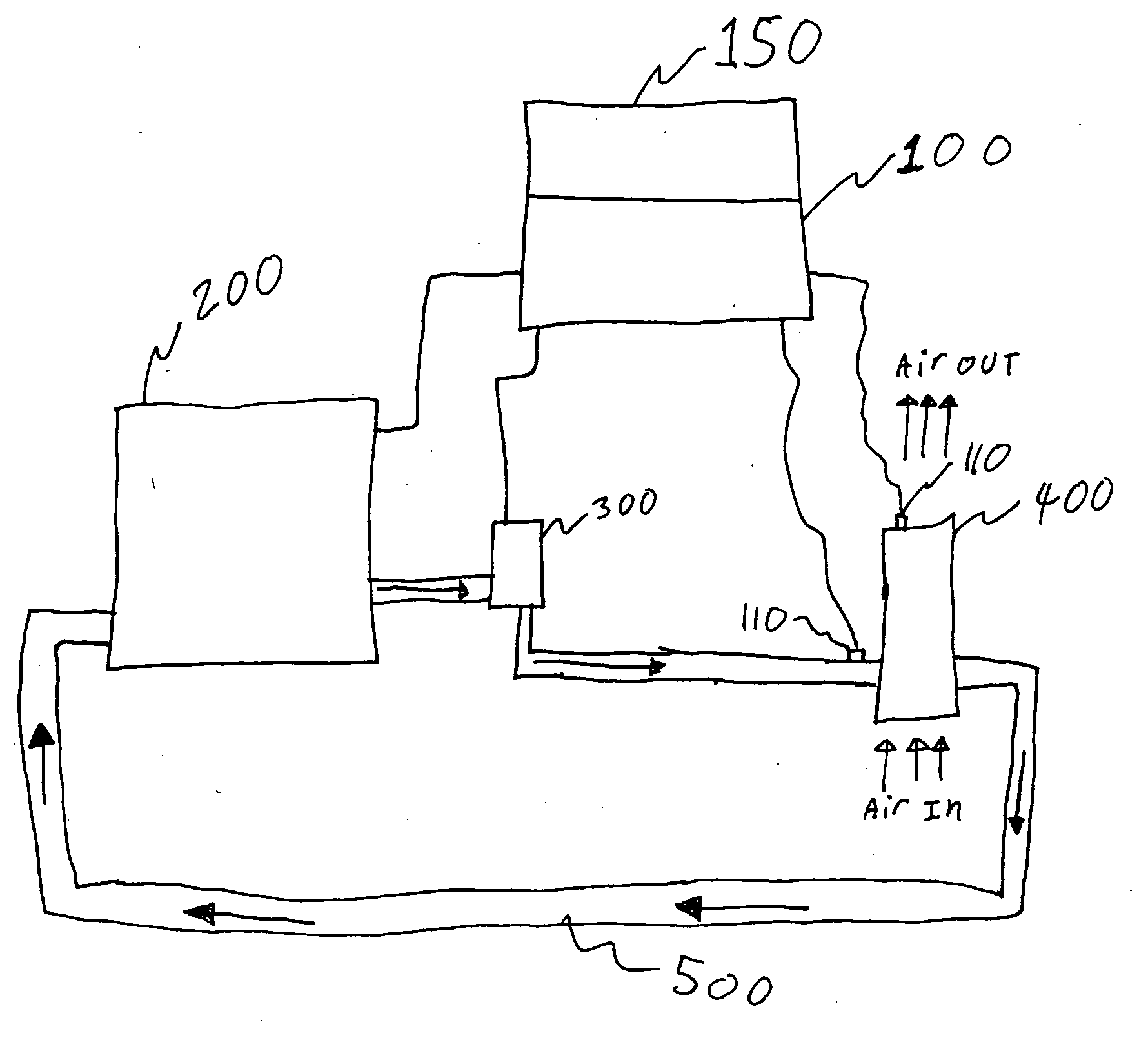
[0021] The present invention provides a system for automatically adjusting the flow rate of engine coolant through a heater core of an automobile (such as but not limited, to a car, an SUV, a minivan, a station wagon, a pickup truck, etc.). More specifically, the present invention permits the flow rate of engine coolant through the heater core of an automobile to be adjusted based on the thermal demand for hot air, produced by the heater core, that is directed into the cabin of an automobile to heat the automobile. To this end, according to a first embodiment of the present invention, the flow rate of engine coolant through the heater core is automatically increased to a higher flow rate for a period of time when the determined temperature difference between the coolant temperature just before the coolant enters the heater core and the temperature of heated air just as it exits the heater core is greater than a predetermined value, thus increasing the amount of heat per unit time th...


PUM


Abstract

A method and apparatus for automatically adjusting the flow rate of engine coolant through a heater core in an automobile by automatically determining a temperature difference between the temperature of coolant at a first flow rate before it enters a heater core and a temperature of air exiting the heater core and automatically increasing the flow rate of the coolant to a second flow rate higher than the first flow rate if the temperature difference is greater than a first predetermined temperature difference.

Description

BACKGROUND OF THE INVENTION [0001] Current climate control systems in automobiles utilize a heater core to heat air that is directed into the cabin of the automobile to provide interior heating. The heater core is typically heated by circulating engine coolant from the engine through the heater core. (Coolant being a term relative to the engine temperature, as the coolant is used to “cool” the engine of the automobile, which is how the coolant obtains the thermal energy used to heat the air passing through the heater core, and thus the coolant is at a high temperature relative to atmospheric temperatures). Typically, the rate of coolant flow through the heater core is governed by various parameters relating to the engine and / or automobile operation and / or coolant pump operation. By way of example, the rate of flow through the heater core may be directly related to engine RPM; the higher the RPM, the higher the coolant flow rate through the heater core. Still further, it may be relat...

Claims


Application Information

Patent Timeline
Patent Type & Authority Applications(United States)
IPC IPC(8): B60H1/00B60H1/08
CPCB60H1/00735B60H1/00885B60H1/08B60H1/0073
Inventor EISENHOUR, RONALD S.
Owner NISSAN MOTOR CO LTD
Why Eureka
Try Eureka