Method and device for driving a matal halide lamp

Inactive Publication Date: 2006-07-20
KONINKLIJKE PHILIPS ELECTRONICS NV
View PDF10 Cites 5 Cited by
  • Summary
  • Abstract
  • Description
  • Claims
  • Application Information

AI Technical Summary

Benefits of technology

[0015] Such a memory allows a manufacturer to implement a certain power characteristic that is preferred by the manufacturer, for instance because it is believed to be an optimal characteristic. However, it may be that non-optimal characteristics are sufficiently satisfactory or acceptable as well. In such case, an elegant and simple embodiment of a lamp driver in accordance with the present invention takes adva

Problems solved by technology

However, it may be that non-optimal characteristics

Method used


Image

  • Method and device for driving a matal halide lamp
  • Method and device for driving a matal halide lamp
  • Method and device for driving a matal halide lamp

Examples


Embodiment Construction

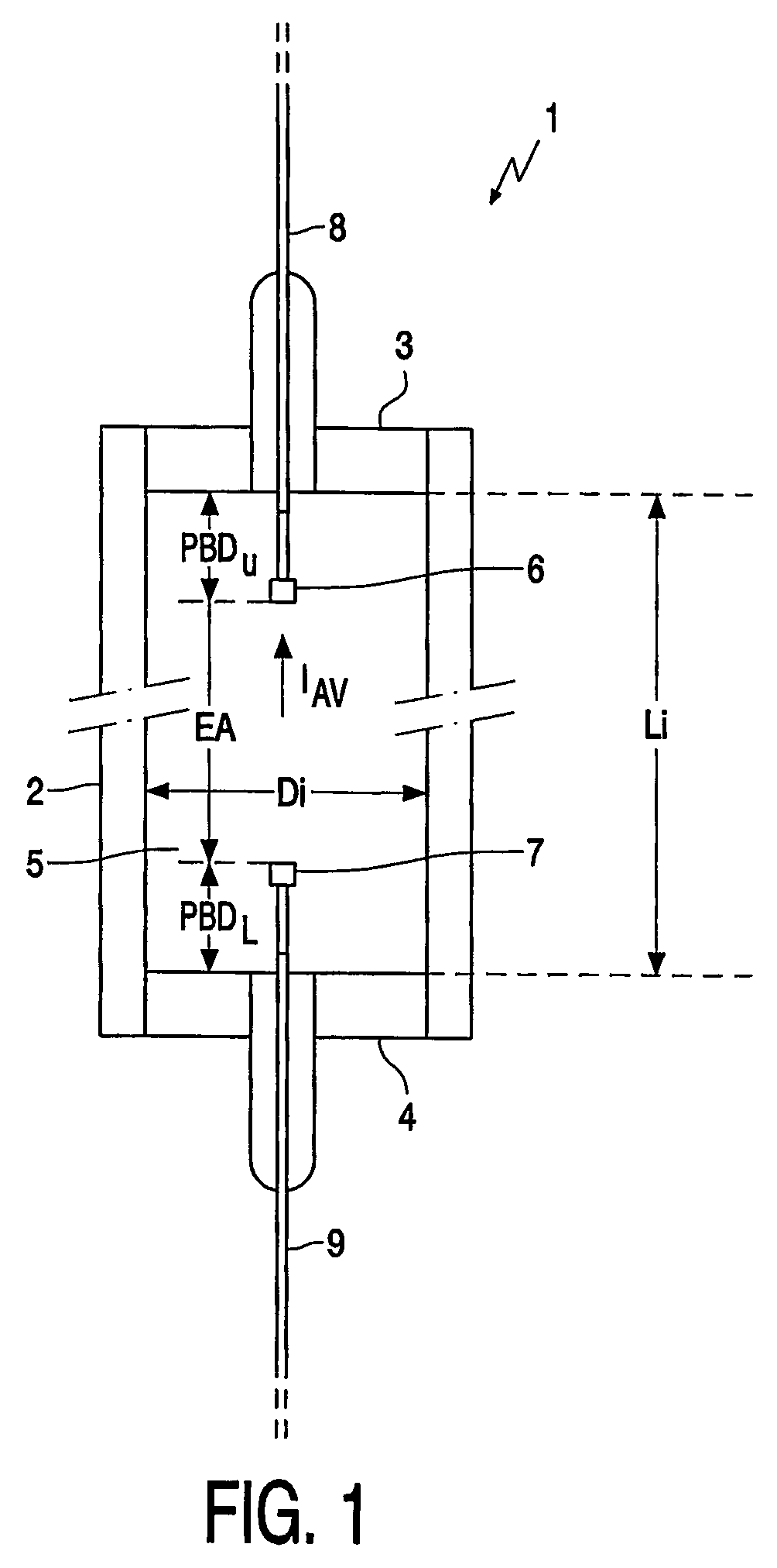
[0024]FIG. 1 schematically shows a possible embodiment of a metal-halide lamp, generally indicated at reference numeral 1. The lamp 1 comprises a light transmissive vessel 2, in the embodiment illustrated having a circular cylindrical shape and having an internal diameter Di; however, other shapes are possible, too. Although not essential in the context of the present invention, the vessel 2 is preferably made from ceramic material; as an alternative, the vessel 2 could be made from quartz. At its longitudinal ends, the vessel 2 is closed in a gas-tight manner by plugs or end caps 3, 4 of a compatible material. The vessel2 and the plugs and / or end caps 3, 4 enclose a discharge chamber 5 having a diameter equal to the internal diameter Di of the vessel 2 and having an axial length Li determined by the distance between the end caps 3 and 4. An aspect ratio AR is defined as the ratio Li / Di.

[0025] Inside the discharge chamber 5, two electrodes 6, 7 are arranged at a mutual distance EA,...


PUM


Abstract

A method is described for driving a gas discharge lamp (1), specifically a HID lamp, more specifically a metal halide lamp, most specifically a metal halide lamp with an aspect ratio larger than 3 or even 4. The lamp is supplied with a commutating DC current having a duty cycle (D) and an average current intensity (IAV) at a certain electrical output power. The method comprises the step of varying the average current intensity (IAV) and the electrical output power in order to vary the color temperature of the lamp. Preferably, the average current intensity (IAV) is changed by changing the duty cycle (D), and the electrical output power is varied in relation to the average current intensity (IAV).

Description

FIELD OF THE INVENTION [0001] The present invention relates in general to a method and device for driving a gas discharge lamp, specifically a HID lamp, more specifically a metal halide lamp. BACKGROUND OF THE INVENTION [0002] Gas discharge lamps are commonly known. In general, they comprise a light transmitting vessel enclosing a discharge chamber in a gastight manner, an ionizable filling and a pair of electrodes located opposite each other in the discharge chamber, each electrode being connected to an associated current conductor which extends from the discharge chamber through the lamp vessel to the exterior. During operation, a voltage is applied over said electrodes, and a gas discharge occurs between said electrodes causing a lamp current to flow between the electrodes. Although it is possible to drive an individual lamp within a relatively wide range of operating currents, a lamp is typically designed for being operated at a specific lamp voltage and lamp current and thus to...

Claims


Application Information

Patent Timeline
IPC IPC(8): H05B39/04H05B41/288H05B41/292H05B41/392
CPCH05B41/2882H05B41/2928H05B41/3928Y02B20/202Y02B20/00
Inventor VERMEULEN, FRANSISCUS ARNOLDUSGEIJTENBEEK, JOHANNES JACOBUS FRANCISCUSHENDRIX, JOHAN LEOPOLD VICTORINA
Owner KONINKLIJKE PHILIPS ELECTRONICS NV
Why Eureka
Try Eureka