Waveguide horn antenna array and radar device
- Summary
- Abstract
- Description
- Claims
- Application Information
AI Technical Summary
Benefits of technology
Problems solved by technology
Method used
Image

Examples
Embodiment Construction
[0053] A waveguide horn antenna array according to an embodiment of the present invention is described with reference to FIGS. 1 to 15.
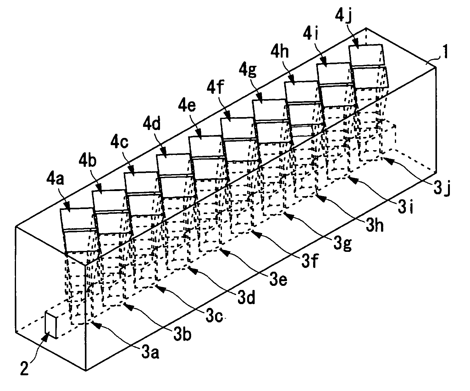
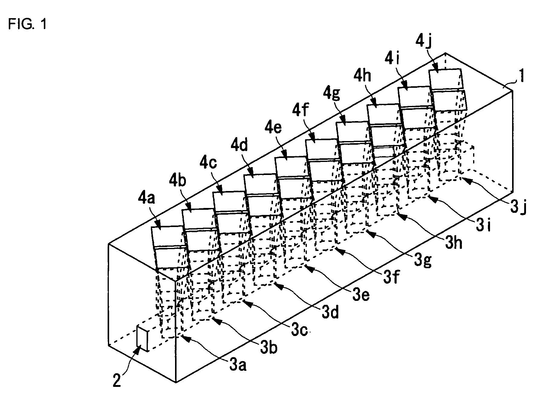
[0054]FIG. 1 is an external perspective view showing the outline of the structure of a waveguide horn antenna array of the present invention. FIG. 2 is a partially expanded perspective view of the waveguide horn antenna array shown in FIG. 1. FIG. 3A is a partially expanded top view of the waveguide horn antenna array shown in FIG. 1, and FIG. 3B is a sectional view taken along line A-A′ in FIG. 3A.
[0055] The waveguide horn antenna array of the present invention contains a feed waveguide 2 extending in a fixed direction and horn antennas 3a to 3j and 4a to 4j each coupled to the feed waveguide 2. The feed waveguide 2 and the horn antennas 3a to 3j and 4a to 4j are formed in a conductor member 1.
[0056] The feed waveguide 2 extends in a fixed direction and is formed in accordance with the shape of the conductor member 1, and the section perpendicula...
PUM
 Abstract
Description
Claims
Application Information
 - R&D
- Intellectual Property
- Life Sciences
- Materials
- Tech Scout
- Unparalleled Data Quality
- Higher Quality Content
- 60% Fewer Hallucinations
Browse by: Latest US Patents, China's latest patents, Technical Efficacy Thesaurus, Application Domain, Technology Topic, Popular Technical Reports.
© 2025 PatSnap. All rights reserved.Legal|Privacy policy|Modern Slavery Act Transparency Statement|Sitemap|About US| Contact US: help@patsnap.com