
Automatic cement mixer

A cement mixer, automatic technology, applied in cement mixing devices, clay preparation devices, chemical instruments and methods, etc., can solve the problems of difficult control of cement viscosity, low work efficiency, poor stability, etc., achieve faster mixing speed, simple structure, good stability effect

Inactive Publication Date: 2016-12-14
太仓圣广仁自动化设备有限公司
View PDF1 Cites 1 Cited by
  • Summary
  • Abstract
  • Description
  • Claims
  • Application Information

AI Technical Summary

Problems solved by technology

[0003] Cement mixer is an important part of the construction industry. It is mainly a mixing equipment for mixing various mortars, materials, cement and adhesives. It is widely used in construction mortar mixing, putty powder mixing, dry powder coating mixing and other fields. The working principle of cement mixer The material enters the equipment through the feed port, and the stirring device rotates and stirs at a high speed, so that the material is tumbling and mixed rapidly in an all-round continuous cycle, and finally the material is discharged through the discharge port. The traditional cement mixer is large in size, poor in stability, and the viscosity of cement Difficult to control, low work efficiency, can not meet the development of today's construction industry, the current construction industry is more and more thirsty for new cement mixers, so the reform and development of cement mixers is of great significance

Method used


Image

  • Automatic cement mixer

Examples


Embodiment Construction

[0013] The present invention will be further described below in conjunction with the accompanying drawings.

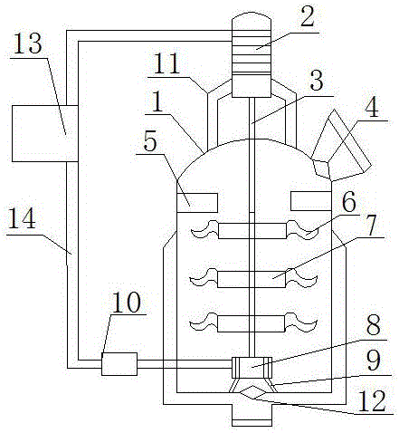
[0014] Such as figure 1 The shown automatic cement mixer includes a housing 1, a stirring shaft 3, an anti-scratch plate 5 and a support rod 9, the outer side of the bottom of the housing 1 is fixedly connected to the discharge port 12, and the top of the housing 1 is fixedly connected to the feed port on the right 4. One end of the stirring shaft 3 is movably connected to the motor 2, and the other end of the agitating shaft 3 is movably connected to the distribution device 8. The distribution device 8 is fixedly connected to the inner side of the bottom of the housing 1 through the support rod 9, and the motor 2 is fixedly connected to the top of the housing 1 through the bracket 11. The scrapers 5 are arranged on both sides of the housing 1 close to the support 11, the stirring shaft 3 is fixedly connected to a plurality of stirring discs 7, the number of which is t...


PUM


Abstract

The invention discloses an automatic cement mixer. The automatic cement mixer comprises a shell, a mixing shaft, scratch-resisting plates and supporting rods. The outer side of the bottom of the shell is fixedly connected with a discharge outlet. The portion, close to the right side, of the top of the shell is fixedly connected with a feed inlet. One end of the mixing shaft is movably connected with one end of a motor; and the other end of the mixing shaft is movably connected with a distributor. The distributor is fixedly connected with the inner side of the bottom of the shell through the supporting rods. The motor is fixedly connected with the top of the shell through a bracket. The scratch-resisting plates are arranged on the two sides inside the shell and close to the bracket. The mixing shaft is fixedly connected with three mixing discs. The two sides of each mixing disc are fixedly connected with mixing blades correspondingly. The automatic cement mixer is simple in structure, small in size and good in stability; a viscosity setting device can be used for effectively setting the viscosity of materials; a digital control device enables the automatic cement mixer to conduct automatic mixing; the use adjustment range is wide, and the precision is high; and the S-shaped mixing blades are reasonable in structural design, mixing is quickened, the working efficiency of equipment is improved, and the automatic cement mixer is easy to promote.

Description

technical field [0001] The invention relates to the technical field of building material operation machinery, in particular to an automatic cement mixer. Background technique [0002] With the rapid economic development in recent years, the civil construction industry is getting hotter and hotter, and the demand for cement is increasing. Mixers are widely used in chemical, construction, food, environmental protection and other industrial production. From the perspective of their operation , Stirring can promote two or more than two kinds of materials to disperse and fully contact with each other, so as to achieve uniform density field, concentration field and temperature field. [0003] Cement mixer is an important part of the construction industry. It is mainly a mixing equipment for mixing various mortars, materials, cement and adhesives. It is widely used in construction mortar mixing, putty powder mixing, dry powder coating mixing and other fields. The working principle ...

Claims


Application Information

Patent Timeline
Patent Type & Authority Applications(China)
IPC IPC(8): B28C5/16B28C5/08
CPCB28C5/16B28C5/0806
Inventor 刘珍秀
Owner 太仓圣广仁自动化设备有限公司
Learn More