

Parallel prosessing of microfluidic devices
a microfluidic device and parallel prosessing technology, applied in the field of synthetic and analytical minimization, can solve the problems of increasing the risk of inaccuracy in the transfer of liquid from the instrument to the individual microchannel structure, affecting the efficiency of microfluidic devices, etc., to achieve the effect of facilitating individual process treatment of the device, facilitating measurement, irradiation etc of part areas, and simplifying individual process treatmen
Inactive Publication Date: 2006-07-20
GYROS
View PDF9 Cites 18 Cited by
- Summary
- Abstract
- Description
- Claims
- Application Information
AI Technical Summary
Benefits of technology
[0015] b) enhanced versatility for the user with respect to the number and the type of microfluidic devices that can be processed in parallel; and / or
[0023] Another object is a microfluidic device that has an inlet arrangement, which simplifies a rapid, reproducible, reliable and accurate loading of well-defined minute liquid volumes to the individual microchannel structures of the device. This object in particular emphasizes volumes in the nl-range, i.e. ≦5,000 nl.
Problems solved by technology
Miniaturization often creates new problems and / or accentuates problems that are easy to handle in larger systems.
Interfacing to a microfluidic device is more difficult the smaller and / or more dense-packed the microchannel structures are.
The risk for inaccuracies in the transfer of liquid from the instrument to the individual microchannel structures increases dramatically when going down in the μl-range, in particular when entering into its lower part (sub-μl-range or nanolitre range, nl-range including picolitre range).
Method used
View moreImage
Smart ImageViewing Examples

Examples
Embodiment Construction
[0152] At the priority date the best mode embodiment corresponds to the variant shown in the drawings.
[0153] The invention is further defined in the appending claims that are part of the specification.
Login to View More PUM
 Abstract
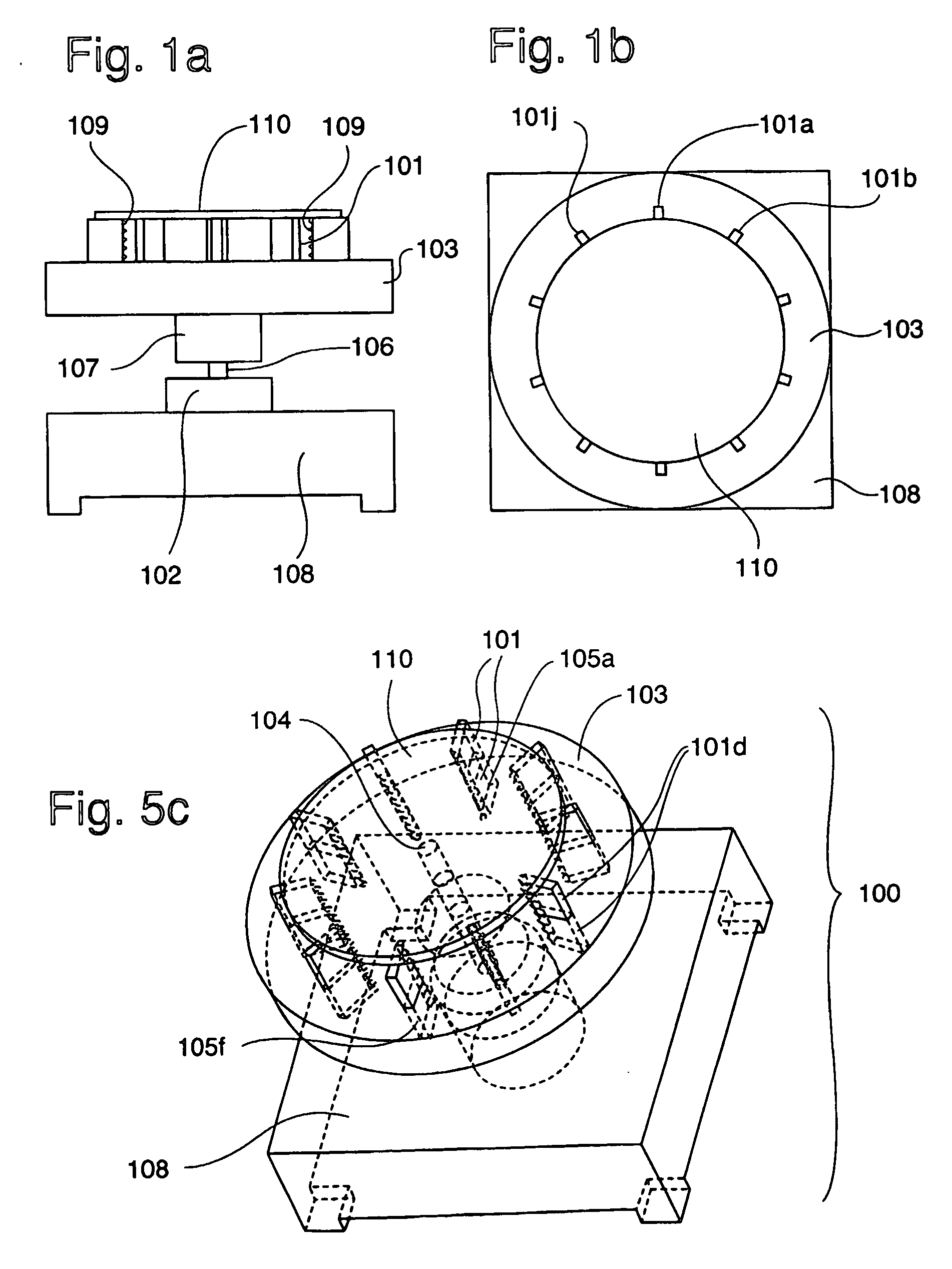
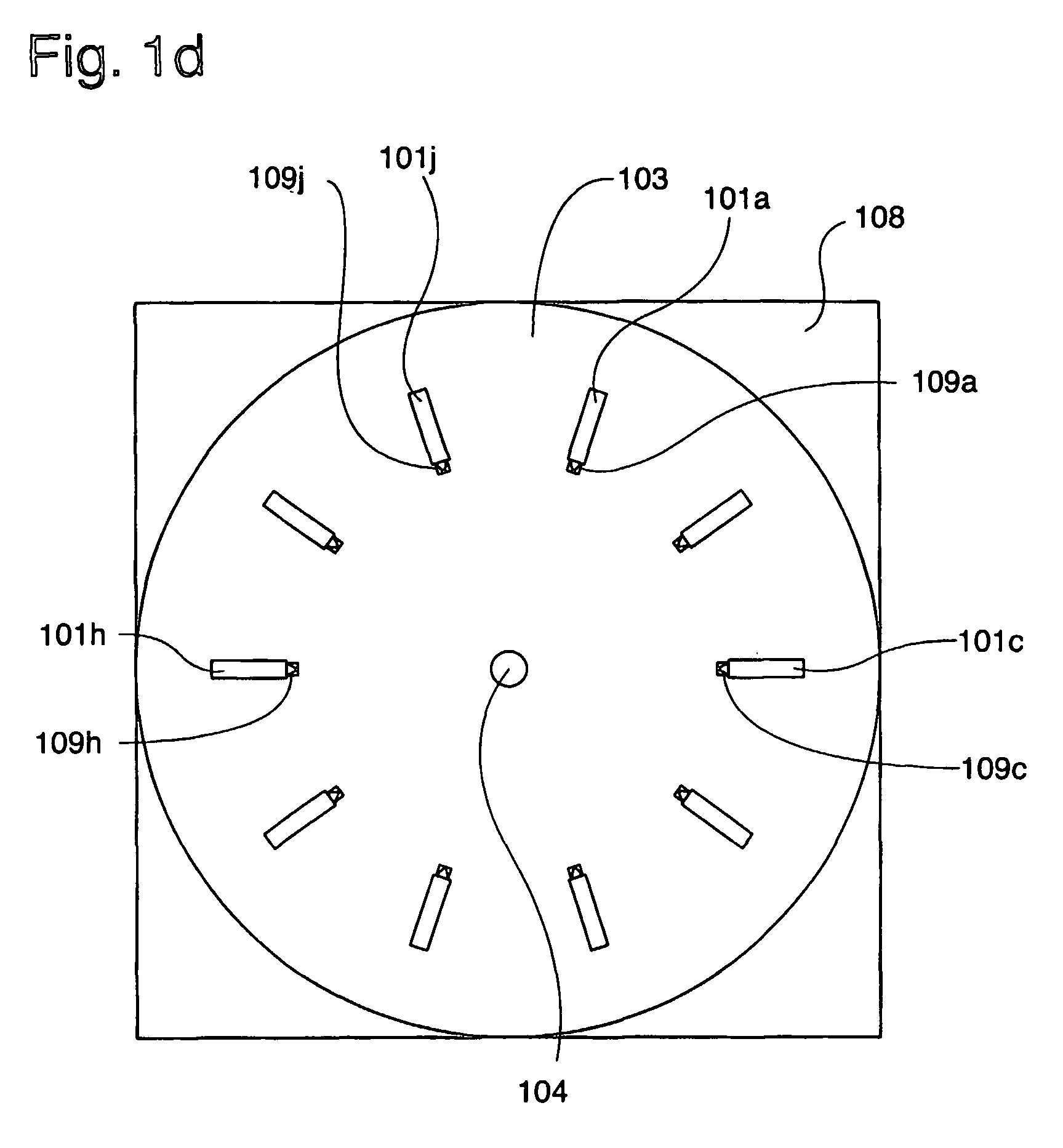
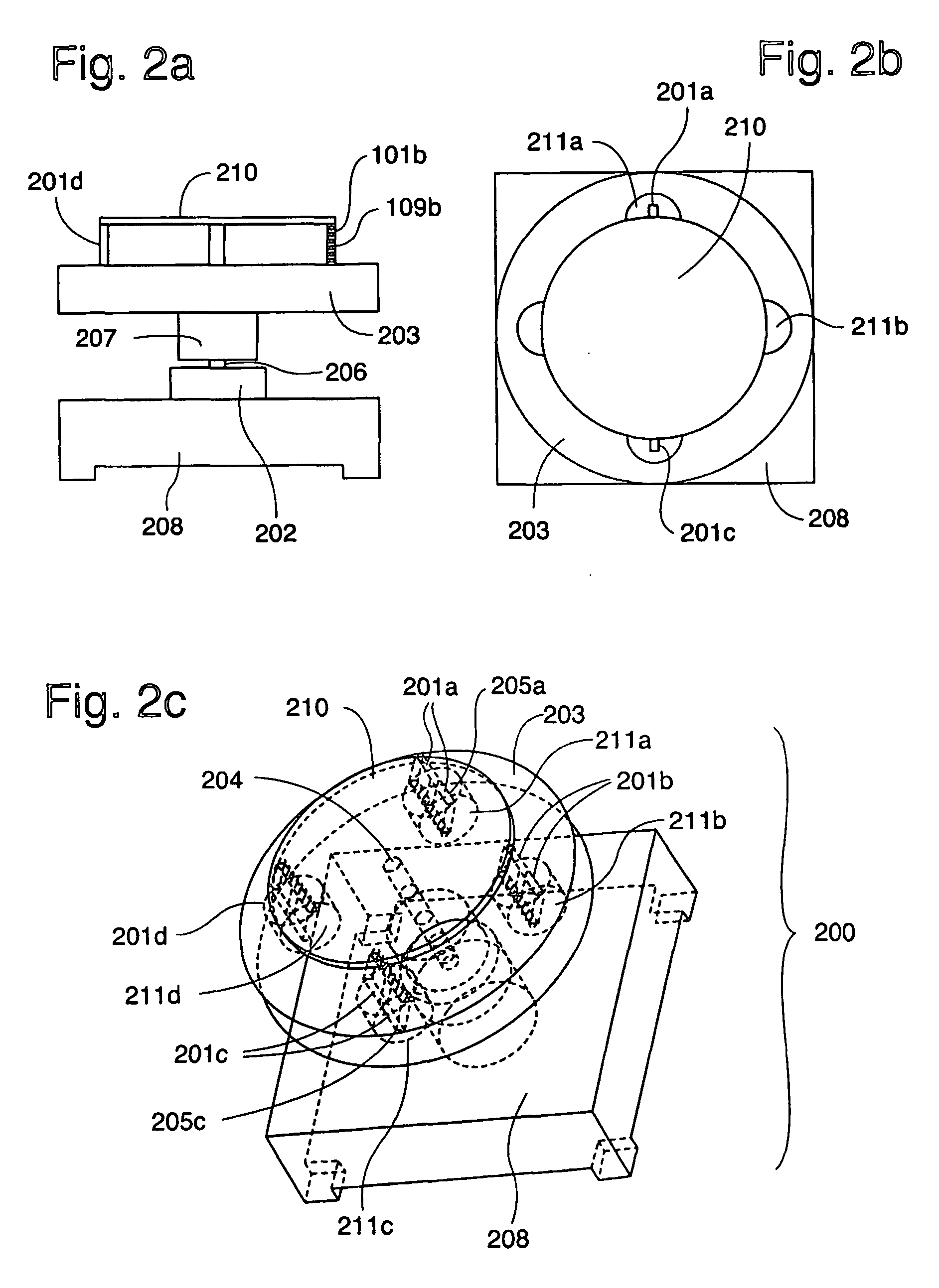
Microfluidic arrangement which comprises A) a number of microfluidic devices, and B) an instrument which comprises a spinner motor and a rotary member arranged such that liquid flow can be driven centrifugal force in each of the devices by spinning the. Each of the microfluidic devices comprises microchannel structures in a common planar layer I. The characteristic feature is that layer I of each device can be oriented radially and at an angle ≠0° relative to the plane of the rotary member, with preference for 90°. The rotary member has seats for holding the devices. A microfluidic device comprising i) two essentially planar and parallel opposite sides, and edge sides, ii) a set of one, two, three or more essentially equal microchannel structures, each of which comprises a first inlet arrangement comprising an inlet port IP I1. The characteristic feature is that a) each of the inlet ports is present in an edge side, and b) the wettability of the inner walls of said first inlet arrangement permits penetration by capillarity of at least a predetermined first volume of an aqueous liquid.
Description
TECHNICAL FIELD [0001] The present invention relates to the miniaturization of analytical, synthetic, preparative etc procedures within chemical and biological sciences. [0002] One aspect of the invention is a microfluidic instrument arrangement, which comprises a) one, two or more essentially equal microfluidic devices, and b) an instrument for processing the microfluidic devices. Additional aspects are: i) the instrument as such, ii) the use of the instrument for processing the microfluidic device (method of processing), iii) a microfluidic device as such, and (iv) a method for loading a predetermined liquid aliquot to each of the microchannel structure of a microfluidic device (“Dip-Chip technology”). The instrument may be used for processing different kinds of microfluidic devices. The microfluidic device may be processed in the innovative instrument but also by the use of other instruments and / or other means. The microfluidic device of item (iii) is adapted to the Dip-Chip tech...
Claims
Login to View More Application Information
Patent Timeline
 IPC IPC(8): C12M1/34B01L3/00G01N35/00
CPCB01L3/5025B01L3/5027B01L3/50273B01L9/527B01L2200/027B01L2200/0605B01L2200/0621B01L2300/0803B01L2300/0816B01L2400/0406B01L2400/0409B01L2400/0487B01L2400/0688G01N35/00029G01N2035/00158G01N2035/00237G01N2035/00504
InventorHOLMQUIST, MATSENGSTROM, JOHAN
OwnerGYROS