FPC connector

a technology of fpc connector and connector plate, which is applied in the direction of coupling contact member, coupling device connection, coupling/disconnecting parts, etc., can solve the problems of not providing reinforcing plate, resistance to plurality of contacts, and difficult to insert fpc into the connector, etc., to achieve the effect of minimizing the mounting area, easy breaking, and reducing the siz

Inactive Publication Date: 2006-07-20
JST MFG CO LTD
View PDF2 Cites 18 Cited by
  • Summary
  • Abstract
  • Description
  • Claims
  • Application Information

AI Technical Summary

Benefits of technology

[0050] As described above, in the ZIF connector for the FPC, in order to minimize the mounting area, there is a tendency to make the pair of protrusions very small. Since this pair of protrusions is integrally formed with the housing from synthetic resin, when force tending to separate the FPC from the connector is applied, the abovementioned pair of protrusions, in a connector whose size has been minimized, is easily broken by shearing force of the pair of engaging convex portions arranged in the FPC.
[0051] In the FPC connector according to the present invention, breakage of the pair of protrusions is prevented by arranging, next to the two flanks of the pair of protrusions, the pair of metal reinforcing plates that have the convex portions that are latched by the protrusions and the engaging convex portions.

Problems solved by technology

Additionally, in recent years, even for the single-sided FPC, in order to lower the profile of the connector, there is a tendency not to provide the reinforcing plate.
A low profile is possible with this type of NON-ZIF FPC connector; however, as described above, in a thin-film FPC that is multi-polar with about 80 poles, there is resistance to the plurality of -contacts, and it is difficult to insert the FPC into the connector.
The addition of a slider to the terminal of an FPC and a mechanism for connecting this slider to the NON-ZIF FPC connectors has been invented; however, the slide thickness alone raises the mounting height of the connector, and this is not suited to the small and thin types of portable electronic devices of recent years.

Method used


Image

  • FPC connector
  • FPC connector
  • FPC connector

Examples


Embodiment Construction

[0067] A best mode for implementing the present invention is explained below, referring to the drawings.

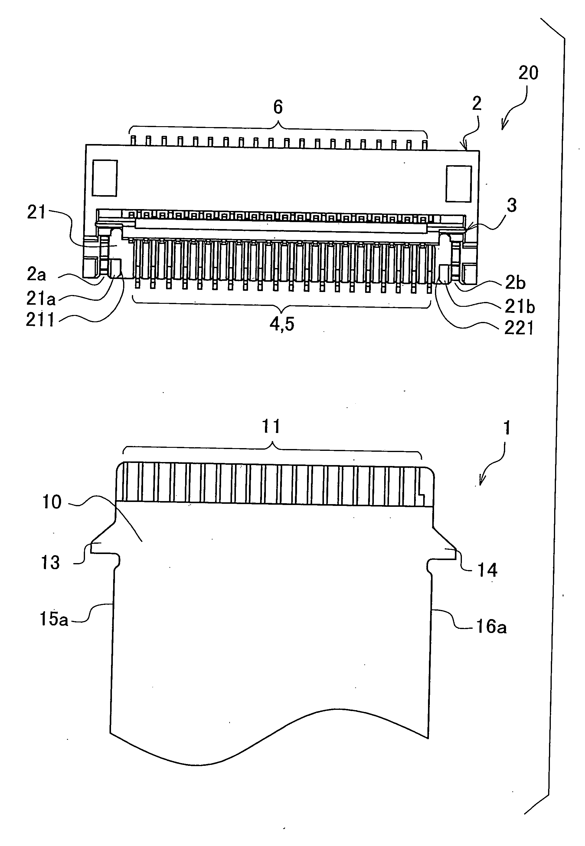
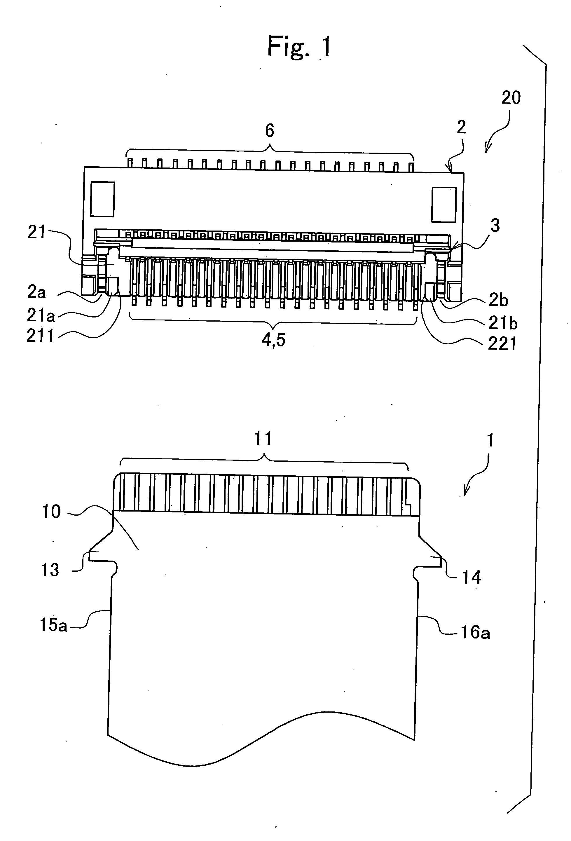
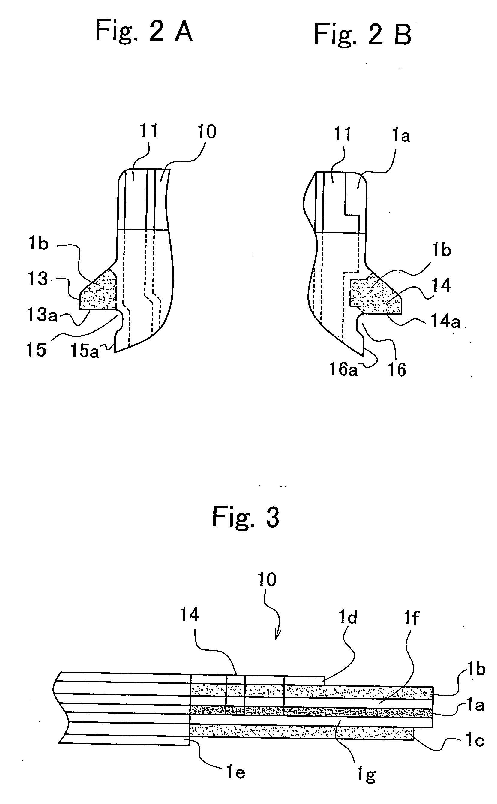
[0068]FIG. 1 is a plan layout view of an embodiment of an FPC connector and an embodiment of an FPC that is connected to the FPC connector, according to the present invention. FIGS. 2A and 2B are enlarged views of main parts of the FPC according to the embodiment. FIG. 2A is an enlarged view including one engaging convex portion, and FIG. 2B is an enlarged view including the other engaging convex portion. FIG. 3 is a side view of the FPC according to the embodiment.

[0069]FIG. 4 is a perspective outline view of the FPC connector according to the embodiment. FIG. 4 is a view with cover-housing in an open state, and is a sectional view of main parts. FIG. 5 is a longitudinal sectional side view of a metal reinforcing plate according to the embodiment, and is a view of a state before the cover-housing is assembled in a housing. FIG. 6 is a longitudinal sectional side view of the met...


PUM


Abstract

An FPC connector comprises: a housing in which is formed a concave portion into which an FPC with a pair of engaging convex portions arranged on two flanks of a terminal portion of the FPC, is inserted; a cover-housing for covering, with opening and closing enabled, the concave portion of the housing, the housing having a pair of protrusions that protrude from a bottom face of the concave portion and are latched by the pair of engaging convex portions; and a pair of metal reinforcing plates, adjoining two flanks of the pair of protrusions, the metal reinforcing plates having convex portions that are latched by the protrusions and the engaging convex portions.

Description

[0001] This application is based on and claims the benefit of priority from Japanese Patent Application No. 2005-009608, filed on Jan. 17, 2005, the content of which is incorporated herein by reference. BACKGROUND OF THE INVENTION [0002] 1. Field of the Invention [0003] The present invention relates to connectors for flexible flat cables-printed circuits that possess flexibility, referred to as FPCs (Flexible Printed Circuits), FFCs (Flexible Flat Cables), and the like. In this specification, a flexible flat cable is generically referred to as an FPC. The present invention relates, in particular, to a connecting structure for an FPC connector and an FPC terminal. [0004] 2. Related Art [0005] In electronic devices in recent years, flexible flat cables (FPCs) are used for connecting printed circuit boards and electronic component modules mounted in portable information devices typified by, for example, DVCs (Digital Video Cameras), DSCs (Digital Still Cameras), cell-phones, and PDAs (...

Claims


Application Information

Patent Timeline
Patent Type & Authority Applications(United States)
IPC IPC(8): H01R13/15
CPCH01R12/774H01R12/79H01R12/88H01R12/89
Inventor MIURA, KAZUTOYAMANE, HIROSHINAKAI, YOSHIYUKITODA, KENICHI
Owner JST MFG CO LTD
Why Eureka
Try Eureka