Scan driver and driving method thereof

a technology of scan driver and driving method, which is applied in the direction of pulse technique, electric analogue store, instruments, etc., can solve the problems of mounting area and increased manufacturing cost of scan driver, and achieve the effect of minimizing manufacturing cost and mounting area, and improving the scan ra

Inactive Publication Date: 2017-04-06
SAMSUNG DISPLAY CO LTD
View PDF13 Cites 4 Cited by
  • Summary
  • Abstract
  • Description
  • Claims
  • Application Information

AI Technical Summary

Benefits of technology

[0010]When a plurality of buffers is mounted in each channel of the scan driver, a mounting area and a manufacturing cost of a scan driver are increased. Accordingly, a method for improving a slew rate while minimizing the mounting area of the scan driver is desired.
[0011]Exemplary embodiments provide a scan driver and a driving method thereof, which may improve a slew rate.
[0022]In the scan driver and the driving method thereof according to exemplary embodiments of the invention, a scan signal is supplied to a specific channel using a buffer located in the specific channel and at least one buffers located in another channel. That is, in exemplary embodiments of the invention, a scan signal is supplied to a specific channel using buffers located in a plurality of channels, and accordingly, the slew rate may be improved. Also, in exemplary embodiments of the invention, one buffer is provided for each channel, and hence it is possible to minimize the manufacturing cost and mounting area of the scan driver.

Problems solved by technology

When a plurality of buffers is mounted in each channel of the scan driver, a mounting area and a manufacturing cost of a scan driver are increased.

Method used


Image

  • Scan driver and driving method thereof
  • Scan driver and driving method thereof
  • Scan driver and driving method thereof

Examples


Embodiment Construction

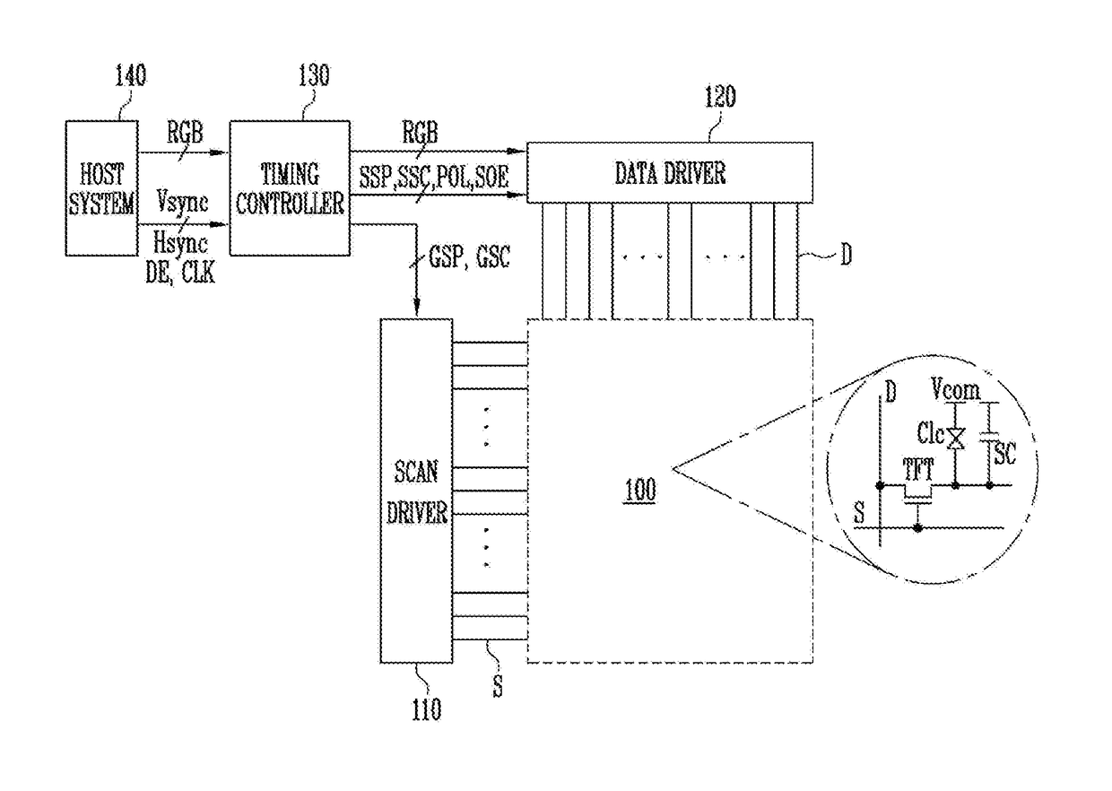
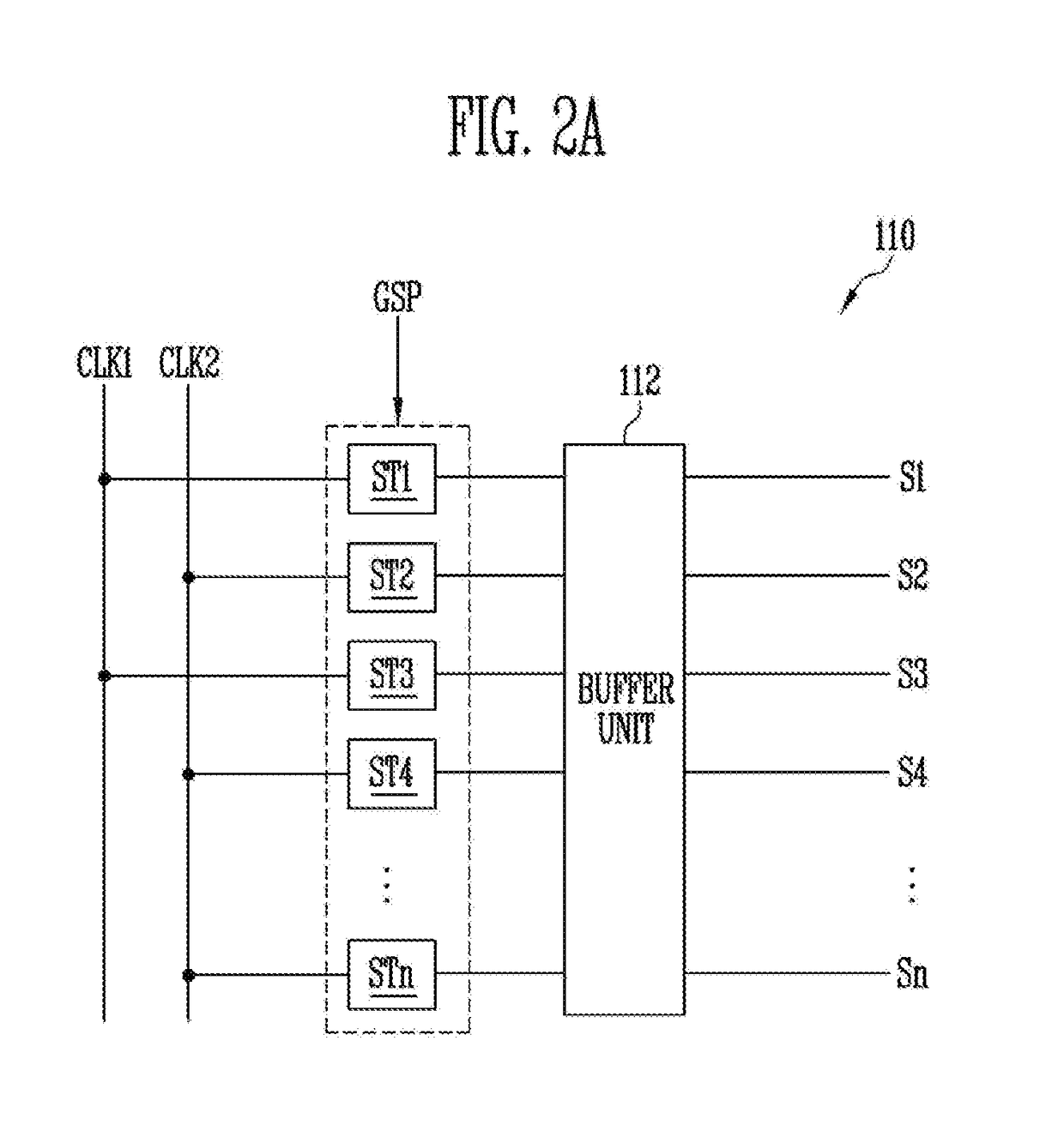
[0033]In the following detailed description, only certain exemplary embodiments of the invention have been shown and described, simply by way of illustration. As those skilled in the art would realize, the described embodiments may be modified in various different ways, all without departing from the spirit or scope of the invention. Accordingly, the drawings and description are to be regarded as illustrative in nature and not restrictive.

[0034]In the entire specification, when an element is referred to as being “connected” or “coupled” to another element, it can be directly connected or coupled to the another element or be indirectly connected or coupled to the another element with one or more intervening elements interposed therebetween. Further, some of the elements that are not essential to the complete understanding of the invention are omitted for clarity. Also, like reference numerals refer to like elements throughout.

[0035]The invention now will be described more fully herei...


PUM


Abstract

A scan driver includes stages respectively located in channels, the stages outputting a sampling signal, corresponding to at least one clock signal, and a buffer unit including buffers respectively located between the stages and scan lines, the buffers each outputting a scan signal to an output terminal thereof, corresponding to the sampling signal supplied through an input terminal thereof where an ith (i is a natural number) buffer located in an ith channel is electrically coupled to at least one specific buffer located in another channel different from the ith channel.

Description

[0001]This application claims priority to Korean Patent Application No. 10-2015-0138690, filed on Oct. 1, 2015, and all the benefits accruing therefrom under 35 U.S.C. §119, the content of which in its entirety is herein incorporated by reference.BACKGROUND[0002]1. Field[0003]Exemplary embodiments of the invention relate to a scan driver and a driving method thereof, and more particularly, to a scan driver and a driving method thereof, which may improve a slew rate.[0004]2. Description of the Related Art[0005]With a development of information technologies, an importance of a display device which is a connection medium between a user and information increases. Accordingly, display devices such as a liquid crystal display device and an organic light emitting display device are increasingly used.[0006]In general, a display device includes a data driver for supplying data signals to data lines, a scan driver for supplying scan signals to scan lines, and a pixel unit including pixels arr...

Claims


Application Information

Patent Timeline
Patent Type & Authority Applications(United States)
IPC IPC(8): G09G3/36H03K17/687H03K5/06H03K3/356
CPCG09G3/3677G09G3/3688H03K3/356H03K17/6871G09G2320/0219G09G2300/0809G09G2310/0291G09G2320/0223H03K5/06G11C19/28G09G2310/0289G11C27/02
Inventor KANG, SUN KOOKIM, TAE GONKIM, KYUNG HALEE, JAE HAN
Owner SAMSUNG DISPLAY CO LTD
Why Eureka
Try Eureka