Method Of Producing A Coin-Type Electrochemical Element And A Coin-Type Electrochemical Element

a technology of electrochemical elements and electrochemical elements, which is applied in the direction of manufacturing tools, cell components, fixed capacitor details, etc., can solve the problems of reducing the reliability of the production process, and affecting the quality of the product. , to achieve the effect of excellent production and minimal mounting area of the printed board

a technology of electrochemical elements and electrochemical elements, which is applied in the direction of manufacturing tools, cell components, fixed capacitor details, etc., can solve the problems of reducing the reliability of the production process, and affecting the quality of the product. , to achieve the effect of excellent production and minimal mounting area of the printed board

US20080089011A1Inactive Publication Date: 2008-04-17PANASONIC CORP

Image

  • Method Of Producing A Coin-Type Electrochemical Element And A Coin-Type Electrochemical Element
  • Method Of Producing A Coin-Type Electrochemical Element And A Coin-Type Electrochemical Element
  • Method Of Producing A Coin-Type Electrochemical Element And A Coin-Type Electrochemical Element

Examples


embodiment 1

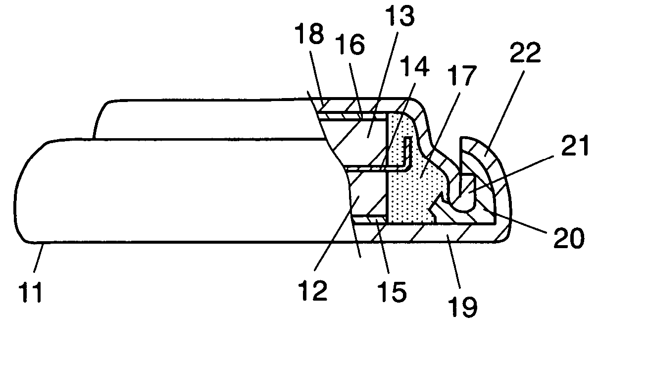
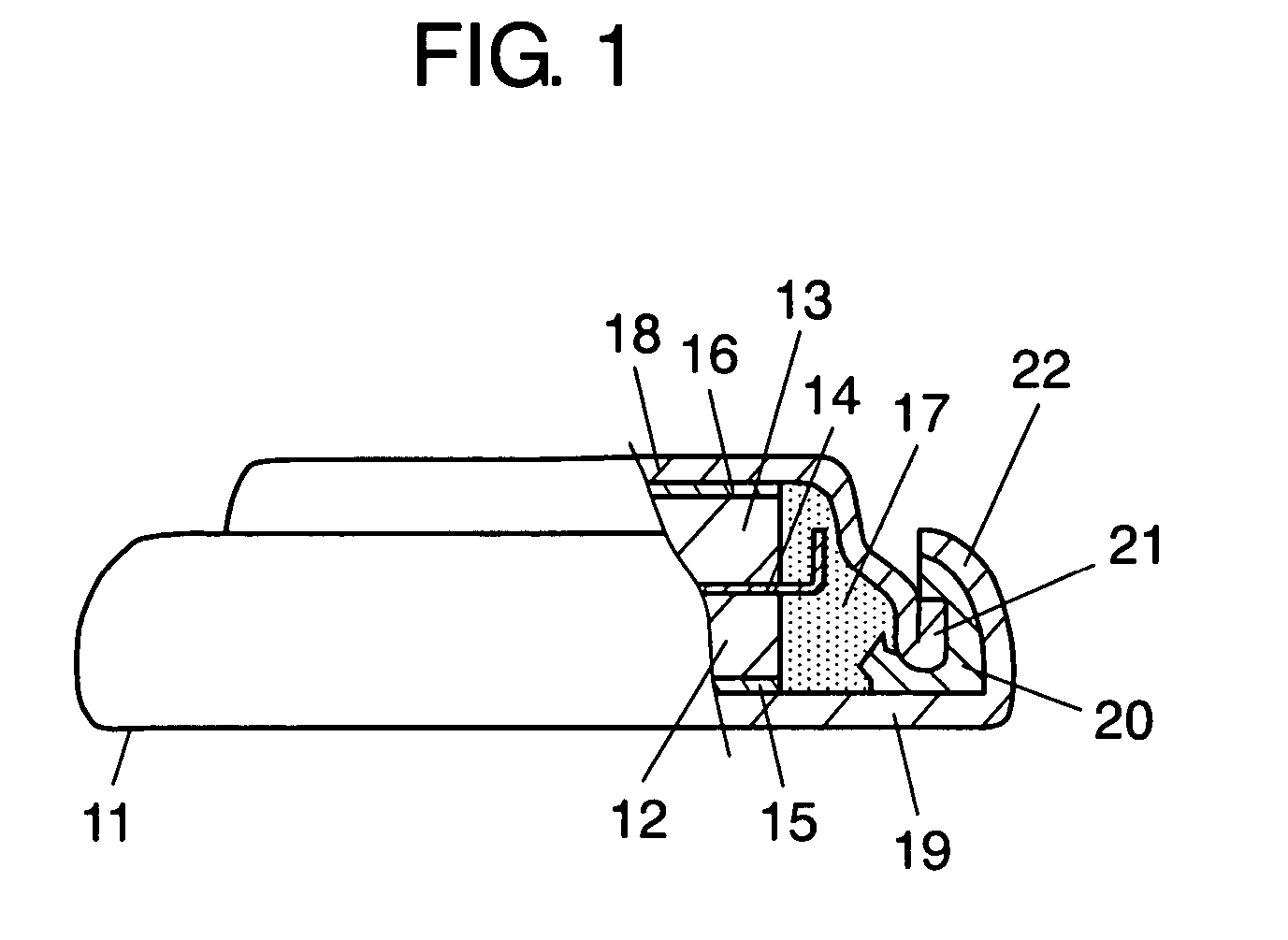
[0054]FIG. 1 is a side view illustrating, in a partly cut-away manner, the constitution of a coin-type electric double layer capacitor for surface mounting. The coin-type electric double layer capacitor 11 includes polarizing electrode 12 comprising an activated carbon electrode on the anode side and polarizing electrode 13 comprising an activated carbon electrode on the cathode side facing each other via separator 14. Polarizing electrode 12 on the anode side is provided with collector 15 for the anode, and polarizing electrode 13 on the cathode side is provided with collector 16 for the cathode. A petroleum coke-type activated carbon powder having an average particle size of 5 μm, carbon black having an average particle size of 0.05 μm as an electric conductivity-imparting agent and a water-soluble binder solution in which a carboxymethyl cellulose is dissolved (concentration: 50%) are mixed together at a weight ratio of 10:2:1, and are kneaded together to a sufficient degree by u...

embodiment 2

[0070]FIGS. 3A and 3B are perspective views of the coin-type electric double layer capacitor according to the embodiment 2.

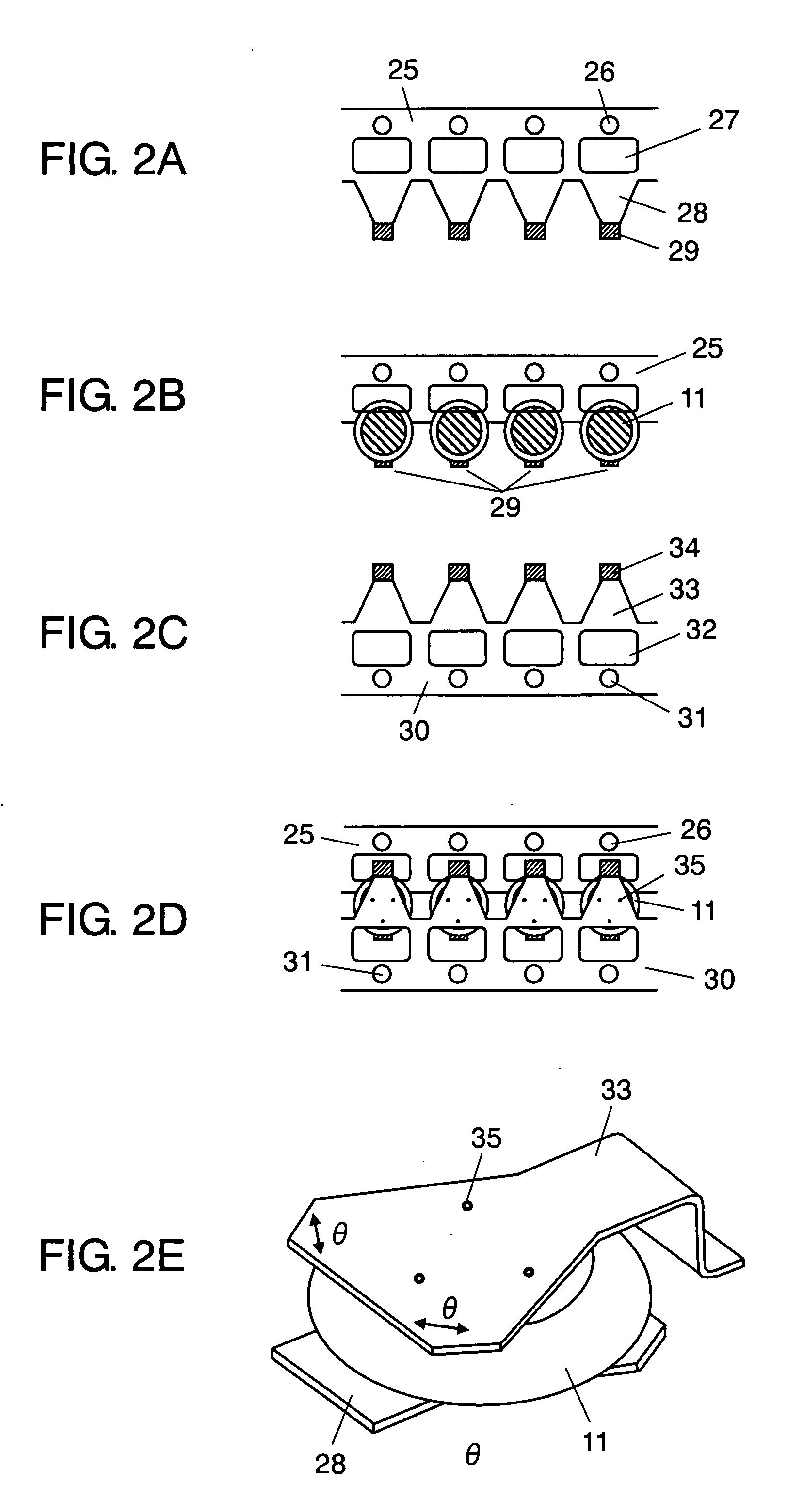
[0071]FIG. 3A illustrates coin-type electric double layer capacitor 11, upper lid portion 18, lower lid portion 19, external lead terminal portion 33 on the cathode side, and external lead terminal portion 28 on the anode side. External lead terminal portions 28 and 33 are nearly of a triangular shape and have a thickness of 0.10 mm. External lead terminal portion 28 of the anode side is spot-welded or laser-welded to lower lid portion 19 of coin-type electric double layer capacitor 11, and external lead terminal 33 of the cathode side is spot-welded or laser-welded to upper lid portion 18 at welding portions 35.

[0072] External lead terminal portion 33 is attached in parallel with external lead terminal portion 28 of the anode side. Further, external lead terminal portion 33 of the cathode side has a portion of external connection surface 36 folded in an L-sha...

example 2

[0083] A coin-type electric double layer capacitor same as that of Example 1 was fabricated according to embodiment 1 while selecting the amount of Ni to be 10.75% by weight, amount of Cr to be 16.84% by weight and amount of Mo to be 2.13% by weight in the stainless steel of lower lid portion 19.


PUM

PropertyMeasurementUnit
diametersaaaaaaaaaa
particle sizeaaaaaaaaaa

Abstract

A coin-type electrochemical element enabling the external lead terminal portions to be accurately and reliably attached to a first lid portion and to a second lid portion of the coin-type electrochemical element, and a method of its production. Coin-type electric double layer capacitor (11) includes first lid portion (19) and second lid portion (18). External lead terminal portions (28) and (33) having a nearly triangular shape are separately connected to the outer surfaces of the lid portions. Upon providing external lead terminal portions (28) and (33) having the triangular shape, welded portion (35) is allowed to have an increased area enabling the coin-type electrochemical element of even a small size to be accurately and reliably welded and making it possible to provide the coin-type electrochemical element having excellent reliability.

Description

TECHNICAL FIELD [0001] This invention relates to a method of producing a coin-type electrochemical element which is used, for example, being mounted on the surface and has external lead terminal portions, and to a coin-type electrochemical element. BACKGROUND ART [0002] As the coin-type electrochemical elements of this type, there have been known an electric double layer capacitor and a button cell. FIG. 4 is a perspective view illustrating, in a partly cut-away manner, the constitution of a conventional electric double layer capacitor. A pair of electric double layer electrodes 41a and 41b are arranged facing each other via insulating separator 44. Electric double layer electrode 41a has disk-like sheet or foil (hereinafter called sheet) 42a, and polarizing electrode 43a which is an activated carbon layer is formed for sheet 42a. Further, electric double layer electrode 41b has sheet 42b, and polarizing electrode 43b which is an activated carbon layer is formed for sheet 42b. [0003...

Claims


Application Information

Patent Timeline
17 Apr 2008
Publication
US20080089011A1
IPC
H01G9/00; B23K26/20; H01M50/109; H01M50/147; H01M50/548; H01M50/559; H01M50/562; H01M50/566
CPC
H01G9/008; H01G9/155; H01M2/0202; Y02E60/13; H01M2/04; H01M2/0465; H01M2/30; H01M2/0222
Inventors
TASEI, MASATOSHI; NIIBO, NARIO