Anisotropic conductive sheet

a technology of anisotropic conductive sheet and conductive sheet, which is applied in the direction of connection contact material, coupling device connection, cap, etc., can solve the problems of shortening the distance between the wires, not easy to surely obtain the fine pitch, and metal wires are susceptible to compressive buckling

Inactive Publication Date: 2006-07-27
JST MFG CO LTD
View PDF4 Cites 27 Cited by
  • Summary
  • Abstract
  • Description
  • Claims
  • Application Information

AI Technical Summary

Benefits of technology

[0013] It is advantageous that noise from junctions between electronic components can be prevented by connecting electronic components such as printed boards, cables and devices which transmit high-frequency signals as well as by ensuring the shield electromagnetic waves property in the elastomer connector. It is also possible to obtain high-admittance if dielectric material provided between signal lines.
[0014] It is also possible to improve the measurement performance by ensuring the shield electro-magnetic waves property in the elastomer connector in the electrical examination on the circuit devices such as printed circuit boards and semiconductor integrated circuits.
[0059] The electrically-conductive second penetrating region, the electrically-conductive sheet-shaped elastomer, and the high-dielectric third penetrating elastomer of such anisotropic conductive sheet respectively correspond to the internal conductor composed of stranded wire (core wire), the outer conductor composed of braiding formed from thin conductive wire, and dielectric material as a spacer between the internal conductor and the outer conductor, and is such that makes the elastomer connector in the junctions between electronic parts high-admittance and ensures the ability thereof to shield electro-magnetic waves.
[0060] In addition, the high-dielectric third penetrating region is formed in a rectangular manner, the electrically-conductive second penetrating region is formed in a rectangular manner, the rectangular third penetrating region and the rectangular second penetrating region is positioned with the same center of gravity, and the present invention makes the elastomer connector in the junctions between electronic parts high-admittance and ensures the ability thereof to shield electro-magnetic waves.

Problems solved by technology

The use of metal wire in the anisotropic conductive elastomer sheet, however, makes it difficult to shorten the distance between the wires, therefore it is not easy to surely obtain the fine pitch that is demanded for anisotropic conductivity in the highly integrated circuit boards and electrical components in recent years.
Metal wires are susceptible to a compressive buckling and may be dropped off from the sheet when used repeatedly such that the anisotropic sheet may not fully conduct performance thereof.
Although inductance and capacitance due to wiring patterns are minimal, these could become more serious for high-frequency applications and cause noise generation.
When high-frequency electric current flows through the wiring patterns, emission of electro-magnetic waves and skin effect may arise and the noise generation may be caused.
However, in elastomer connectors, the above described may not be applied such that it is desirable to obtain an elastomer connector which hardly causes noise generation and the like in high-frequency applications.

Method used


Image

  • Anisotropic conductive sheet
  • Anisotropic conductive sheet
  • Anisotropic conductive sheet

Examples


Embodiment Construction

[0079] Although the embodiments of the present invention are described hereafter, with reference to the drawings, the present invention is not limited to the present embodiments since the present embodiments show concrete materials and numerical values as preferred examples. Hereafter, like elements are designated to like numerical references and explanations thereof are omitted or simplified.

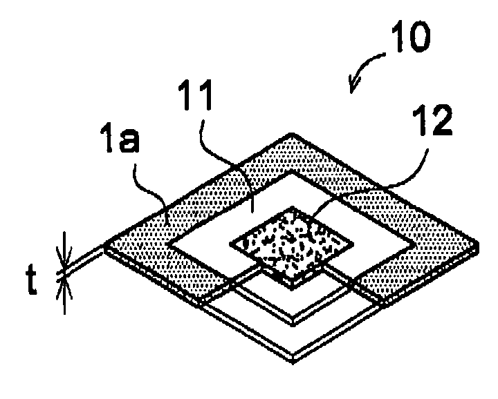
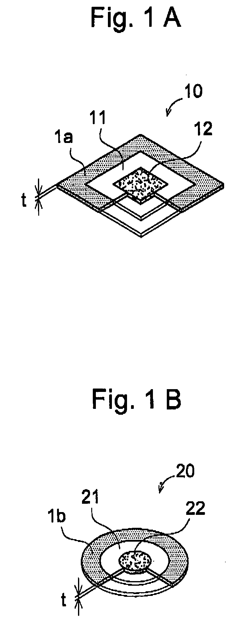
[0080]FIG. 1A is an appearance diagram of a rectangular anisotropic conductive sheet according to a first embodiment of the present invention, and FIG. 1B is that of a circular anisotropic conductive sheet according to a second embodiment of the present invention. Anisotropic conductive sheets 10 and 20 are sheet-shaped and respectively comprise electrically-conductive sheet-shaped elastomer 1a and 1b. A non-conductive first penetrating region 11 is formed in the anisotropic conductive sheet 10 such as to be surrounded by the sheet-shaped elastomer 1a. Similarly, a non-conductive first penetra...


PUM


Abstract

An anisotropic conductive sheet for high frequencies is provided as elastomer for connecting high-integrated circuit boards and fine pitch electronic components of recent years. Anisotropic conductive sheet (30) has a sheet-shaped elastomer (1c), and a non-conductive rectangular first penetrating region (11) is formed vertically and horizontally in a state surrounded by the sheet-shaped elastomer (1c). In addition, an electrically-conductive second penetrating region (12) is formed in a rectangular manner in a state surrounded by the first penetrating region (11). The first penetrating region 11 can be a high-dielectric rectangular third penetrating region. The anisotropic conductive sheet (30) has an effect in that electrostatic shield is provided between connected electronic components.

Description

FIELD OF THE INVENTION [0001] The present invention relates to an anisotropic conductive sheet disposed between circuit boards such as printed circuit boards and various circuit components. RELATED ART [0002] In recent years, more and more electronic devices have reduced their sizes and widths and it has become dramatically desirable to implement a connection between small circuits or a connection between a small component and a small circuit. As examples of such connections, there may be solder joining or joining with anisotropic conductive adhesives. In another example, an anisotropic conductive elastomer sheet may be disposed between an electronic component and a circuit board for conduction of electricity therebetween. [0003] An anisotropic conductive elastomer sheet may be referred to as an elastomer sheet that has conductivity in a certain direction only. Some anisotropic conductive elastomer sheets exhibit conductivity only in a direction of width, and others in the direction...

Claims


Application Information

Patent Timeline
Patent Type & Authority Applications(United States)
IPC IPC(8): B67B3/10H01R4/58H01R11/01H01R13/03H01R13/24
CPCH01R4/58H01R13/2414H01R13/03H01R11/01
Inventor HASEGAWA, MIKI
Owner JST MFG CO LTD
Why Eureka
Try Eureka