Diffuser for an annular combustion chamber, in particular for an airplane turbine engine

a technology of diffusing device and annular combustion chamber, which is applied in the direction of liquid fuel engine, machine/engine, lighting and heating apparatus, etc., can solve the problems of not being suitable for feeding a single-head combustion chamber and not being suitable for use in an engine of relatively small size, so as to minimize the disturbance and minimize the head loss

Active Publication Date: 2006-07-27
SN DETUDE & DE CONSTR DE MOTEURS DAVIATION S N E C M A
View PDF10 Cites 22 Cited by
  • Summary
  • Abstract
  • Description
  • Claims
  • Application Information

AI Technical Summary

Benefits of technology

[0004] An object of the present invention is to provide a diffuser with a separator that is compact so as to be suitable for use in an engine of size that is relatively smaller than in the prior art, and that makes it possible to split optimally the flow of air leaving the compress

Problems solved by technology

It is not suitable for feeding a single-head combustion chamber, in particular for an engine of relatively small size.
That

Method used


Image

  • Diffuser for an annular combustion chamber, in particular for an airplane turbine engine
  • Diffuser for an annular combustion chamber, in particular for an airplane turbine engine
  • Diffuser for an annular combustion chamber, in particular for an airplane turbine engine

Examples


Embodiment Construction

[0019] In the drawings, the left-hand side is upstream or towards the front and the right-hand side is downstream or towards the rear.

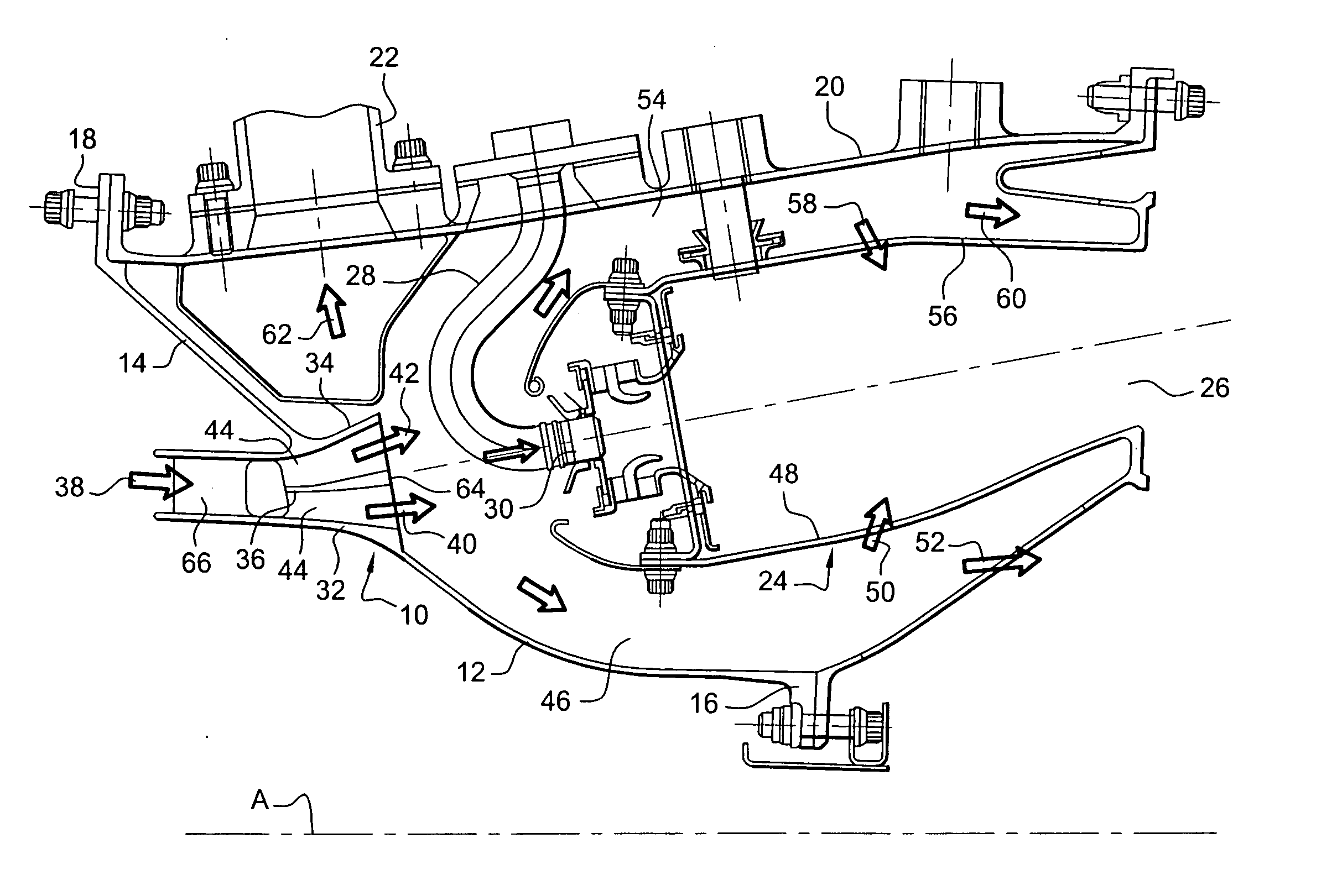
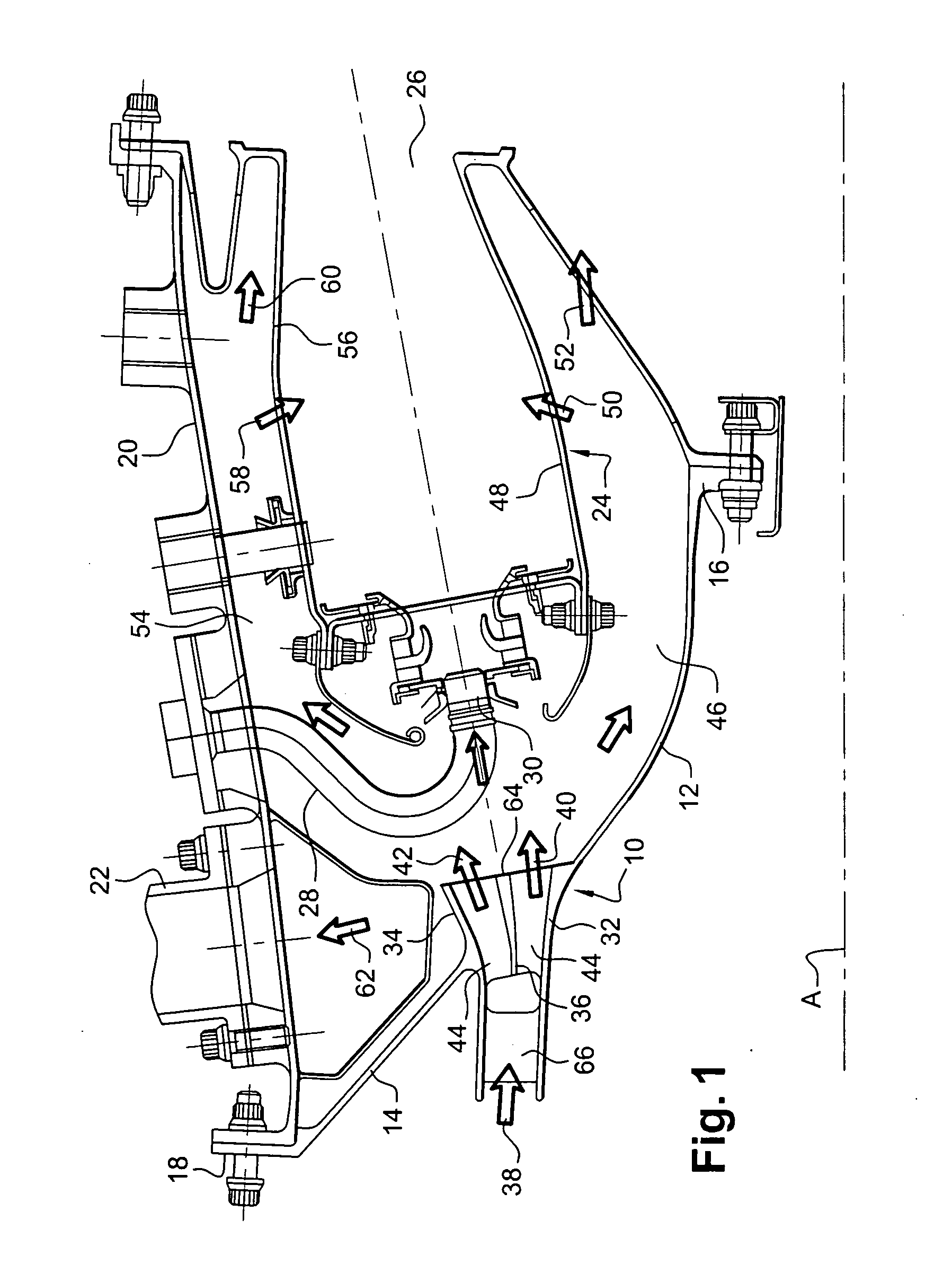
[0020] In FIG. 1, the diffuser 10 of the invention is arranged at the outlet from a compressor (not shown), and it is supported by an inner wall 12 and an outer wall 14 that are secured by flanges 16 and 18 respectively to an inner turbine casing and to an outer turbine casing 20 including at least one duct 22 for taking airplane air (air for pressurizing the cabin, air for de-icing the engine pod, etc.) which opens out upstream from a combustion chamber 24 of annular shape that is fed with air by the diffuser 10 and that itself feeds a high pressure turbine (not shown) arranged downstream from the outlet 26 of the combustion chamber.

[0021] The outer casing 20 also carries ducts 28 for feeding fuel to injectors 30 that are distributed around a circumference about the longitudinal axis A of the combustion chamber 24 and of the engine.
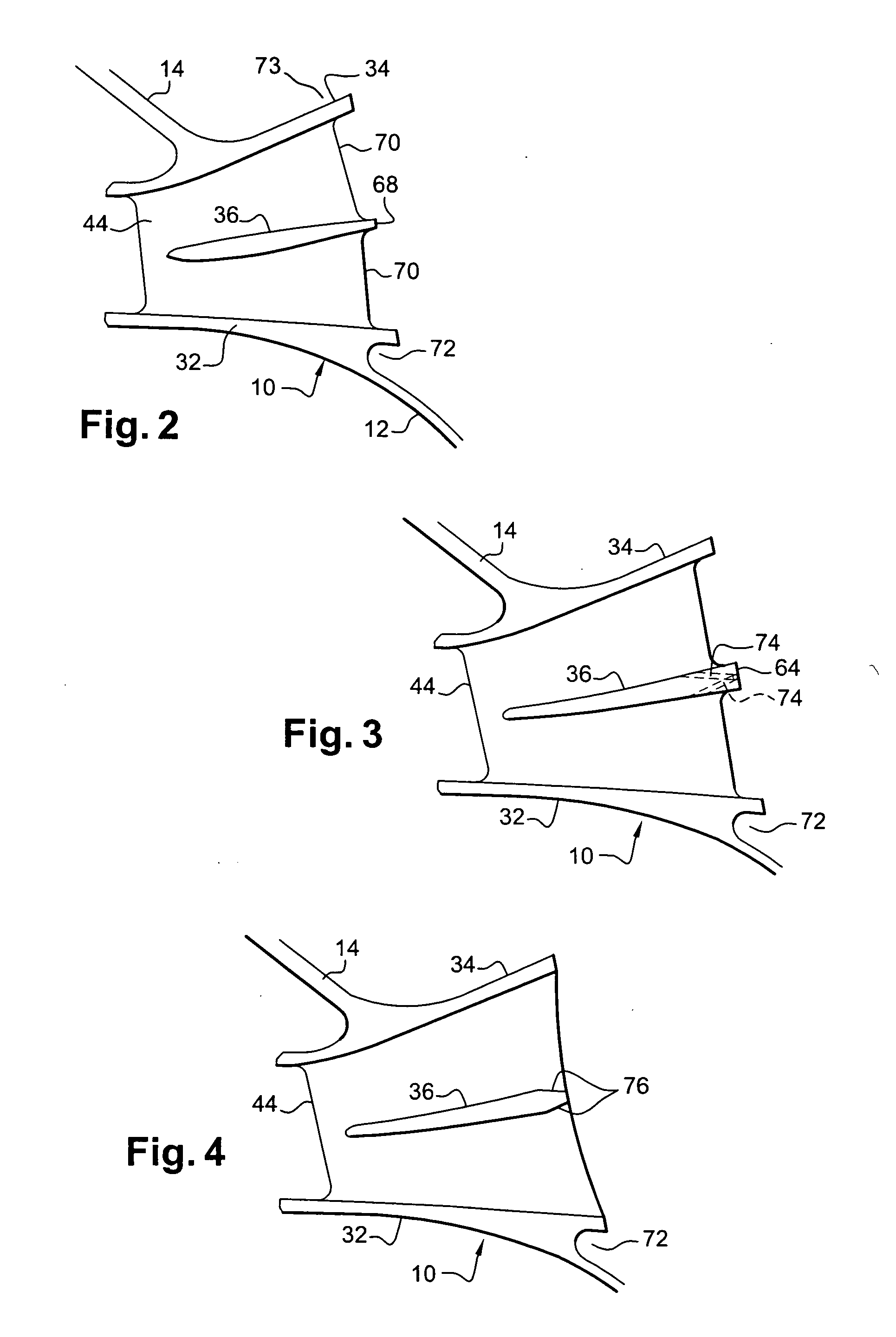
[0022] The diff...


PUM


Abstract

A diffuser for a single-head annular combustion chamber of an airplane engine, the diffuser comprising a separator formed by a thin sheet connected by structural arms to inner and outer circularly-symmetrical walls of the diffuser, the diffuser angle for each diffusion stream defined by the separator lying in the range about 12° to about 13°.

Description

[0001] The invention relates to a diffuser for an annular combustion chamber, in particular for an airplane engine such as a turbojet or a turboprop, the diffuser comprising a separator for splitting the flow of air leaving a compressor into two annular diffusion streams feeding the combustion chamber. BACKGROUND OF THE INVENTION [0002] A diffuser of that type is already known for feeding a double-headed combustion chamber, i.e. a combustion chamber having two concentric annular sets of fuel injectors. The separator comprises two circularly symmetrical surfaces of revolution that diverge downstream away from the inlet to the diffuser. That structure has a very open configuration and is for engines of large size. It is not suitable for feeding a single-head combustion chamber, in particular for an engine of relatively small size. [0003] A diffuser is also known comprising two coaxial separators arranged one around the other to split the flow of air leaving the compressor into three c...

Claims


Application Information

Patent Timeline
IPC IPC(8): F23R3/42
CPCY02T50/675F01D9/041F04D29/542F23R3/04F23R3/50Y02T50/671Y02T50/673F04D29/544Y02T50/60
Inventor CAYRE, ALAINDAGUENET, LUC HENRI, CLAUDEGAUTIER, CLAUDEPIEUSSERGUES, CHRISTOPHETOUCHAUD, STEPHANE HENRI, GUY
Owner SN DETUDE & DE CONSTR DE MOTEURS DAVIATION S N E C M A
Why Eureka
Try Eureka