Heat pipe with screen mesh wick structure

a technology of wick structure and heat pipe, which is applied in the field of heat pipe, can solve the problems of reducing the speed of condensed working fluid, limiting the heat transfer performance of heat pipe, and not always the best way to choose a screen mesh having small pores, etc., and achieves a large capillary pressure and reduces the flow resistance of condensed fluid.

Inactive Publication Date: 2006-07-27
HON HAI PRECISION IND CO LTD
View PDF9 Cites 32 Cited by
  • Summary
  • Abstract
  • Description
  • Claims
  • Application Information

AI Technical Summary

Benefits of technology

[0008] A heat pipe in accordance with a preferred embodiment of the present invention comprises a pipe body having an inner wall and a screen mesh disposed on the inner wall of the pipe body. The screen mesh is in the form of a multi-layer structure with at least one layer thereof has an average pore size different from that of the other layers. The layer with large-sized pores is capable of reducing the flow resistance to the condensed fluid to flow back, whereas the layer with small-sized pores is still capable of providing a relatively large capillary pressure for the condensed fluid in the heat pipe.

Problems solved by technology

However, it is not always the best way to choose a screen mesh having small-sized pores, because the flow resistance to the condensed working fluid also increases due to the decrease in pore size of the screen mesh.
The increased flow resistance reduces the speed of the condensed working fluid in returning back to the evaporating section and therefore limits the heat transfer performance of the heat pipe.
As a result, a heat pipe with a screen mesh that has too large or too small pore size often suffers dry-out problem at the evaporating section as the condensed fluid cannot be timely return back to the evaporating section of the heat pipe.

Method used


Image

  • Heat pipe with screen mesh wick structure
  • Heat pipe with screen mesh wick structure
  • Heat pipe with screen mesh wick structure

Examples


first embodiment

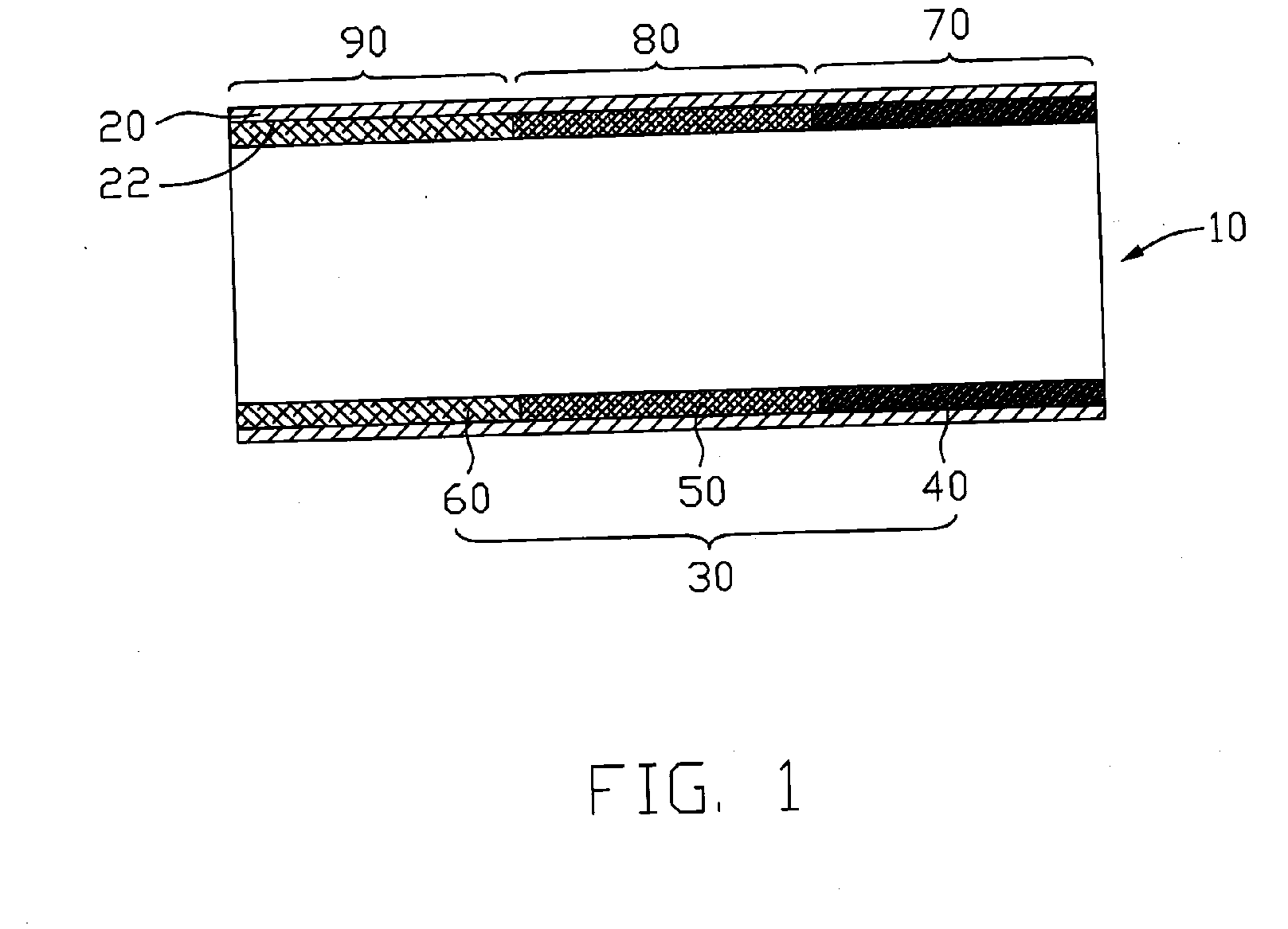
[0020]FIG. 1 illustrates a heat pipe 10 in accordance with the present invention. The heat pipe 10 comprises a pipe body 20 and a screen mesh 30 disposed on an inner wall 22 of the pipe body 20. The heat pipe 10 comprises an evaporating section 70 and a condensing section 90 at respective opposite ends thereof, and an adiabatic section 80 located between the evaporating section 70 and the condensing section 90.

[0021] The pipe body 20 is typically made of high thermally conductive materials such as copper or copper alloys. The screen mesh 30 is saturated with a working fluid (not shown), which acts as a heat carrier for carry thermal energy from the evaporating section 70 toward the condensing section 90 when undergoing phase change from a fluid state to a vaporous state. The working fluid may be water, alcohol or other material having a low boiling point and the heat pipe 10 is vacuumed; thus, the working fluid can easily evaporate to vapor during operation.

[0022] Along a longitudi...

fourth embodiment

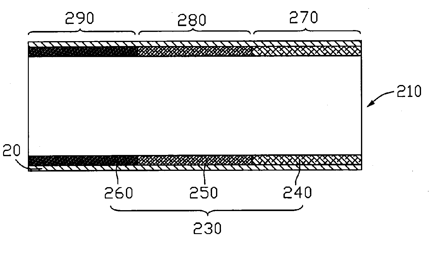
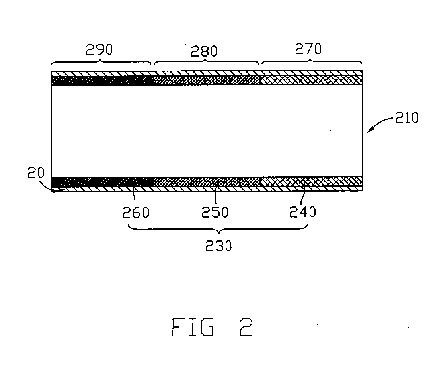
[0025]FIG. 4 illustrates a heat pipe 410 according to the present invention. The heat pipe 410 includes a pipe body 20 and a screen mesh 430 arranged in the pipe body 20. The screen mesh 430 is in the form of a multi-layer structure, which comprises an outer layer 440, an intermediate layer 450 and an inner layer 460. These layers 440, 450, 460 are stacked together along a radial direction of the pipe body 20 with the outer layer 440 abutting the inner wall 22 of the pipe body 20. Each layer of the screen mesh 430 has an average pore size different from that of the other layers, and these layers 440, 450, 460 are stacked together in such a manner that the average pore sizes thereof gradually increase along the radial direction from the inner wall 22 of the pipe body 20 towards a central axis X-X of the pipe body 20.

[0026] According to the above-mentioned general rule, the capillary pressure of a wick and its flow resistance to the condensed fluid increase due to a decrease in pore s...

seventh embodiment

[0029]FIG. 7 illustrates a heat pipe 710 according to the present invention. The heat pipe 710 comprises a screen mesh 730 having the outer, intermediate and inner layer 740, 750, 760 arranged along a radial direction of the pipe body 20. Each layer comprises three sections arranged along the longitudinal of the heat pipe 710. The outer layer 740 is divided into a first section 67, a second section 68 and a third section 69 corresponding to the evaporating, adiabatic and condensing section 770, 780, 790 of the heat pipe 710, respectively. Similar to the outer layer 740, the inner layer 760 comprises a first, second and third section 47, 48, 49, and the intermediate layer 750 comprises a first, second and third section 57, 58, 59. Each section of a specific layer has an average pore size different from that of the other sections of the specific layer. Thus the screen mesh 730 is in the form of multi-layer structure either along the longitudinal direction or along the radial direction...


PUM


Abstract

A heat pipe (10) includes a pipe body (20) having an inner wall (22) and a screen mesh (30) disposed on the inner wall of the pipe body. The screen mesh is in the form of a multi-layer structure with at least one layer thereof having an average pore size different from that of the other layers. The layer with large-sized pores is capable of reducing the flow resistance to the condensed fluid to flow back, whereas the layer with small-size pores is capable of providing a relatively large capillary pressure for drawing the condensed fluid from the condensing section to the evaporating section.

Description

FIELD OF THE INVENTION [0001] The present invention relates generally to a heat pipe as a heat transfer device, and more particularly to a heat pipe with a screen mesh wick structure. DESCRIPTION OF RELATED ART [0002] As electronic industry continues to advance, electronic components such as central processing units (CPUs), are made to provide faster operation speeds and greater functional capabilities. When a CPU operates at a high speed, its temperature frequently increases greatly. It is desirable to dissipate the heat generated by the CPU quickly. [0003] To solve this problem of heat generated by the CPU, a cooling device is often used to be mounted on top of the CPU to dissipate heat generated thereby. It is well known that heat absorbed by fluid having a phase change is ten times more than that the fluid does not have a phase change; thus, the heat transfer efficiency by phase change of fluid is better than other mechanisms, such as heat conduction or heat convection. Thus a h...

Claims


Application Information

Patent Timeline
Patent Type & Authority Applications(United States)
IPC IPC(8): F28D15/02
CPCF28D15/046
Inventor HONG, CHU-WANWU, JUNG-YUANCHENG, CHING-TAILO, CHANG-TING
Owner HON HAI PRECISION IND CO LTD
Why Eureka
Try Eureka