[0011] An object of the present invention, which was made to solve the above-mentioned problems, is therefore to provide a heat exchange plate, which permits to optimize a pattern of irregularity of
heat transfer sections to cope with a problem of difference in characteristic properties of fluids that flow on the opposite surfaces of the plate, respectively, and ensure sufficient heat transfer performance, thus obtaining a
high heat exchange efficiency.
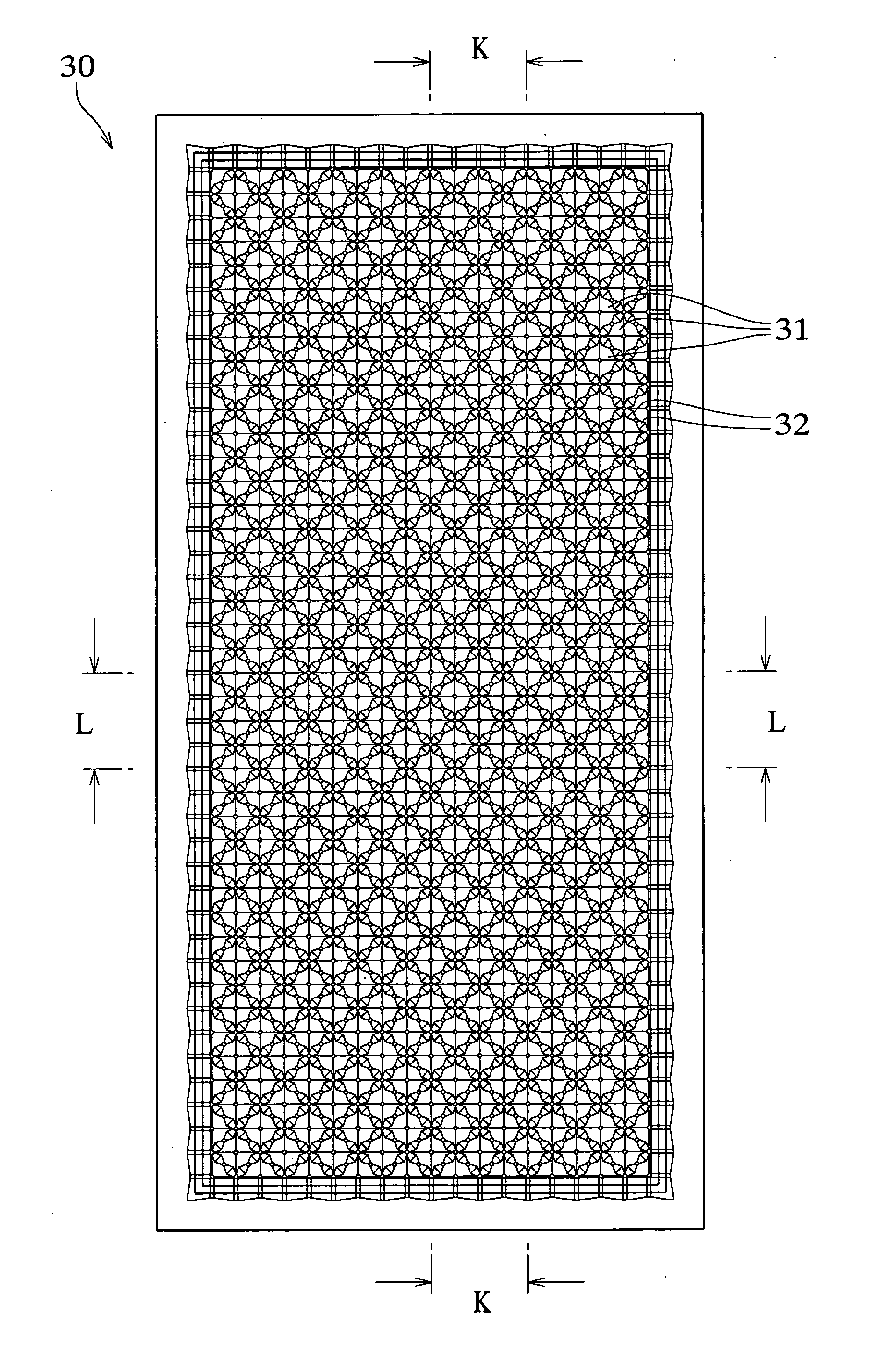
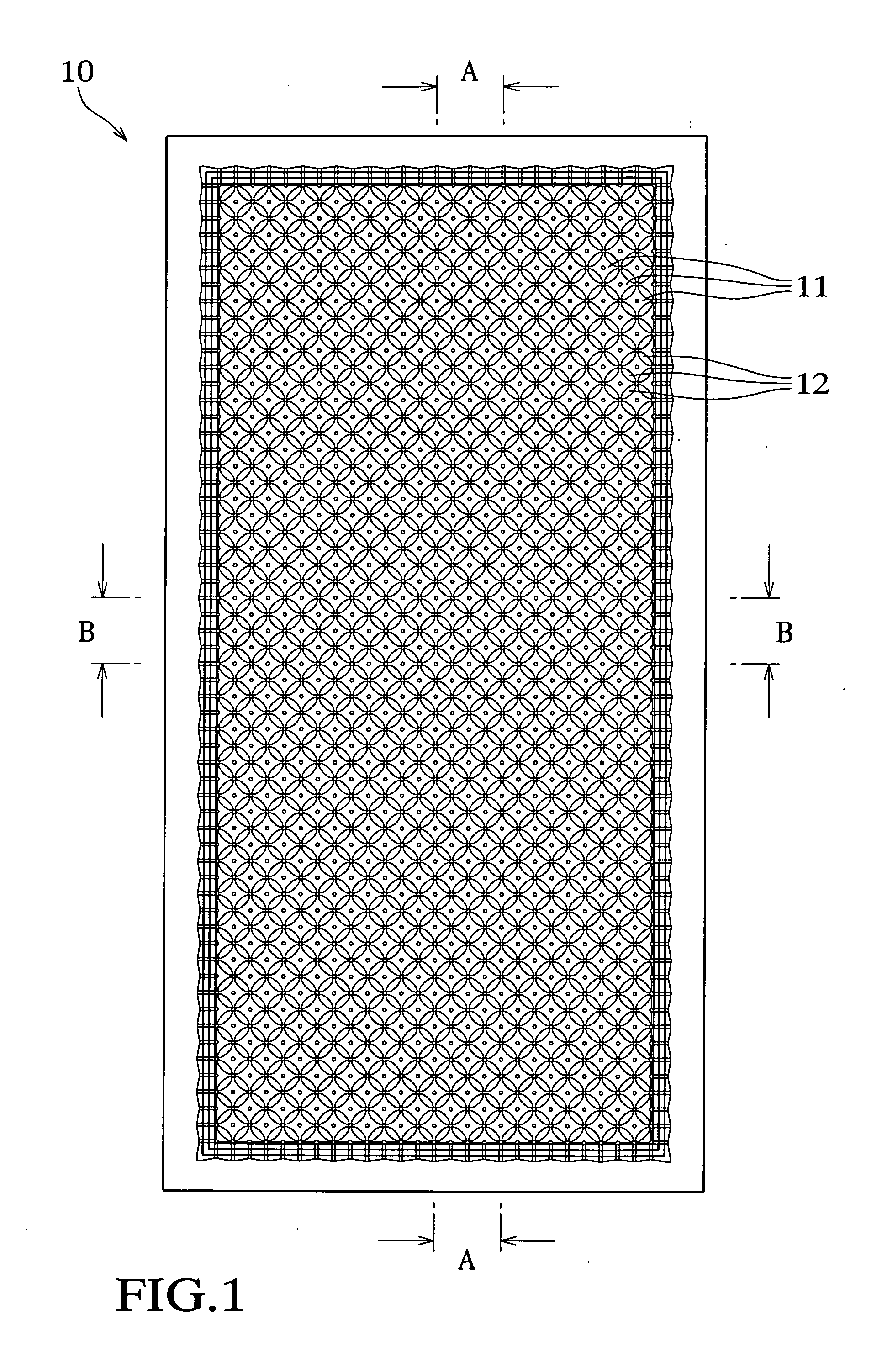
[0013] According to the first aspect of the present invention, the heat exchange plate has the pattern of irregularity in which the main protrusions and the intermediate protrusions are formed on the metallic plate. When the heat exchange plate is combined to the other heat exchange plate having the same structure so that they face each other on the same side and the tops of the main protrusions of the former plate come into contact with the corresponding tops of the main protrusions of the latter plate, or projections formed on the rear sides of the recesses surrounded by the main and intermediate protrusions of the former plate come into contact with corresponding projections formed on the rear sides of the recesses surrounded by the main and intermediate protrusions of the latter plate, to form a combined unit, and then the thus formed combined unit is combined to the other combined units in the same manner, a gap in which wide and narrow areas repeatedly continue along lines along which the protrusions are aligned on the plate is formed between the respective adjacent two plates. As a result, the gaps having different configuration and size are provided on the opposite surfaces of the plate. Such gaps provide different passages, thus achieving different heat transfer performance. As a result, appropriate selection of the passages in accordance with characteristic property of the heat exchange fluids makes it possible to progress heat transfer between the plate and the respective fluids in a remarkably effective manner, thus providing an effective heat exchange between the heat exchange fluids. In addition, gaps between the protrusions extend linearly on straight lines along which the protrusions are aligned, while expanding and reducing in a repeated manner, to form passage sections so that the passage section intersects the other passage section so as to communicate therewith, thus providing a braided passage structure. Even when a flowing relationship of the heat exchange fluids is based on any one of a parallel flowing
system, a counter-flowing
system and a cross flowing
system, it is therefore possible to cause the heat exchange fluids to behave in flow in substantially the same manner to provide substantially the same heat transfer performance. In addition, even when the heat exchange fluids flow on the basis of any combination of the flowing directions, it is possible to make smoothly heat exchange with low pressure-loss and enhance degree of freedom in design of a heat exchanger, thus providing excellent versatility.
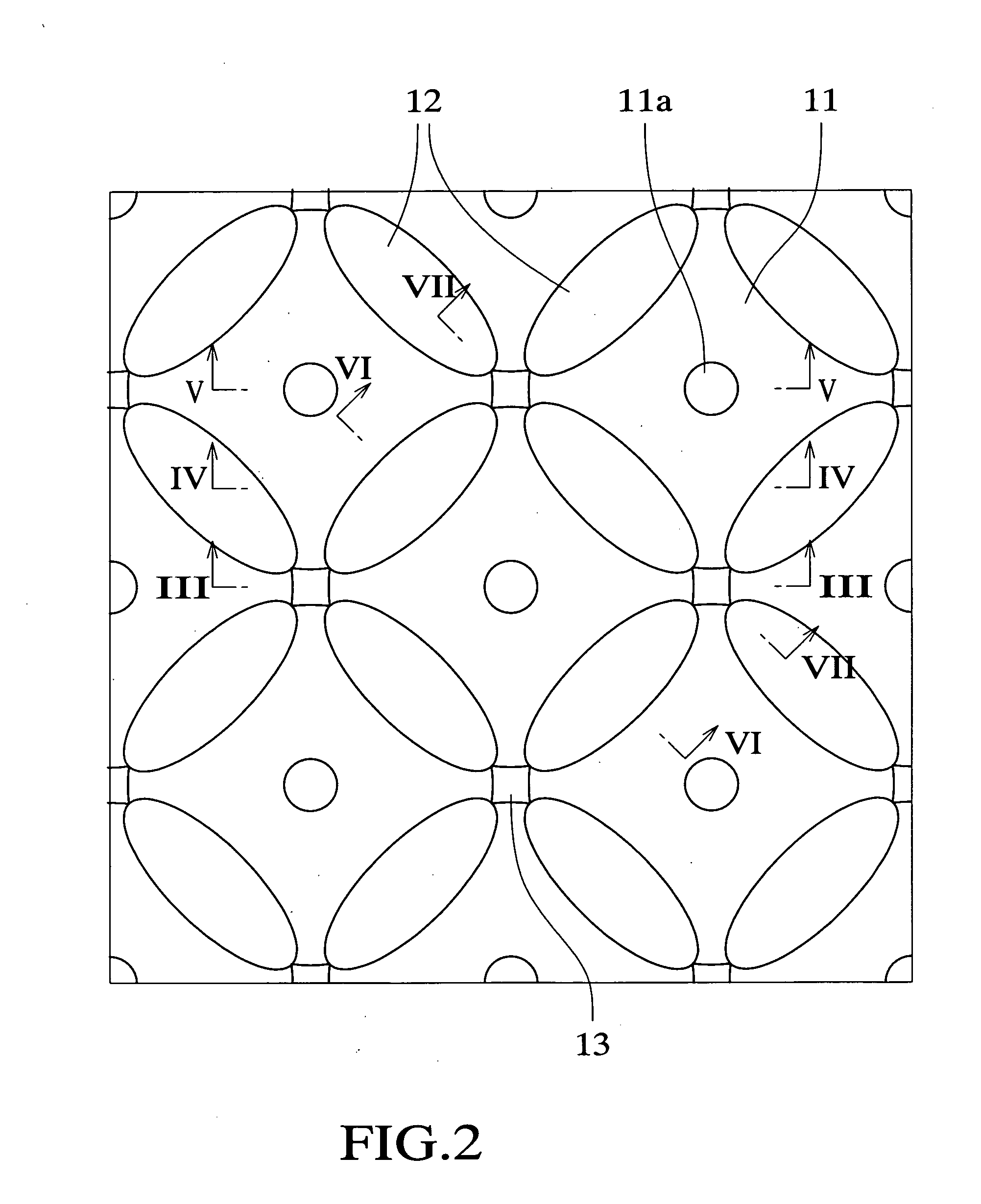
[0015] According to the second aspect of the present invention, the plate is constructed in the combined form of curved bodies by defining each of the main protrusions by the truncated cone and each of the intermediate protrusions by the one or more curved portions. It is therefore possible to reduce pressure loss and achieve smooth flow of the heat exchange fluids and smooth heat transfer, thus improving heat exchange efficiency. In addition, such a curved structure permits dispersion of force applied to the plate, thus enhancing strength to cope with a fluid having a
high pressure and improving
formability. When
seawater is used as one of the heat exchange fluids, which is introduced into the passage between the plates, such a curved structure prevents
fouling from attaching thereto, thus avoiding deterioration of performance for a long period of time.
[0017] According to the third aspect of the present invention, the plate is constructed in the combined form of flat surface bodies by defining each of the main protrusions by the truncated
pyramid and each of the intermediate protrusions by the one or more flat portions. It is therefore possible to provide an easier design of the heat transfer sections of the plate and easily impart suitable heat exchange properties for the respective heat exchange fluids to the plate. In addition, it is possible to easily manufacture the plate, thus reducing costs.
[0019] According to the fourth aspect of the present invention, the height of the intermediate protrusion is decreased to create variation in configuration of the passages provided on the opposite surfaces of the plate so that the height of the passage provided above the intermediate protrusion is smaller than the height of the passage provided below the intermediate protrusion. As a result, it is possible to create variation in flow rate and flow velocity of the heat exchange fluids respectively flowing the adjacent passages between which the plate is placed. This can cope with a case where the two kinds of heat exchange fluids with which heat exchange is to be made are remarkably different from each other in amounts of the fluids flowing into and discharging from the heat exchanger, to achieve heat transfer without loss, thus improving the heat exchange efficiency. The passage having the smaller height is provided below the intermediate protrusion so as to increase the flowing velocity of the fluid, thus achieving effective progress of heat transfer and more remarkably improving the heat exchange efficiency.
[0021] According to the fifth aspect of the present invention, the heat exchange plate has the pattern of irregularity in which the main protrusions are provided in the form of truncated cone on the metallic plate. When the heat exchange plate is combined to the other heat exchange plate having the same structure so that they face each other on the same side and the tops of the main protrusions of the former plate come into contact with the corresponding tops of the main protrusions of the latter plate, or projections formed on the rear sides of the recesses surrounded by the main protrusions of the former plate come into contact with corresponding projections formed on the rear sides of the recesses surrounded by the main protrusions of the latter plate, to form a combined unit, and then the thus formed combined unit is combined to the other combined units in the same manner, a gap in which wide and narrow areas repeatedly continue along lines along which the main protrusions are aligned on the plate is formed between the respective adjacent two plates. As a result, the gaps having different configuration and size are provided on the opposite surfaces of the plate. Such gaps provide different passages, thus achieving different heat transfer performance. As a result, appropriate selection of the passages in accordance with characteristic property of the heat exchange fluids makes it possible to progress heat transfer between the plate and the respective fluids in a remarkably effective manner, thus providing an effective heat exchange between the heat exchange fluids. In addition, gaps between the protrusions extend linearly on straight lines along which the protrusions are aligned, while expanding and reducing in a repeated manner, to form passage sections so that the passage section intersects the other passage section so as to communicate therewith, thus providing a braided passage structure. Even when a flowing relationship of the heat exchange fluids is based on any one of a parallel flowing system, a counter-flowing system and a cross flowing system, it is therefore possible to cause the heat exchange fluids to behave in flow in substantially the same manner to provide substantially the same heat transfer performance. In addition, even when the heat exchange fluids flow on the basis of any combination of the flowing directions, it is possible to make smoothly heat exchange with low pressure-loss and enhance degree of freedom in design of a heat exchanger, thus providing excellent versatility.

