Cylinder head gasket

Inactive Publication Date: 2006-07-27
ISHIKAWA GASKET CO LTD
View PDF5 Cites 12 Cited by
  • Summary
  • Abstract
  • Description
  • Claims
  • Application Information

AI Technical Summary

Benefits of technology

[0020] According to the cylinder head gasket of the present invention, since suppress around the cylinder bores can be eq

Problems solved by technology

On the other hand, recently, with the improvement of fuel consumption and enhancement of antipollution measures, there is a tendency of miniaturization of the automobile engine.
Since the engine offers excellent productivity, there is a tendency that the mini-aluminum engine could become the main due to the production cost.
Measures to control the deformation

Method used


Image

  • Cylinder head gasket
  • Cylinder head gasket
  • Cylinder head gasket

Examples


Embodiment Construction

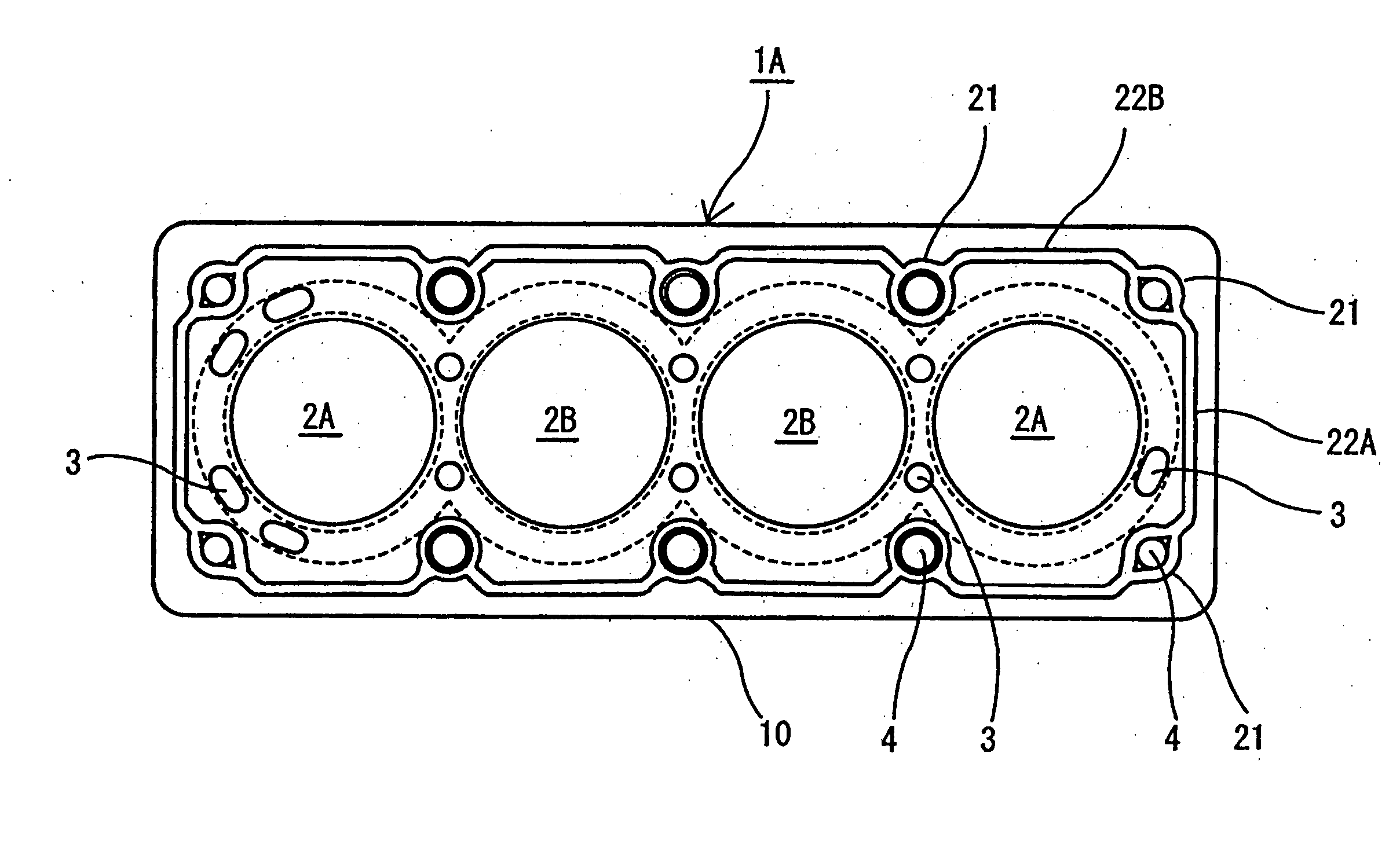
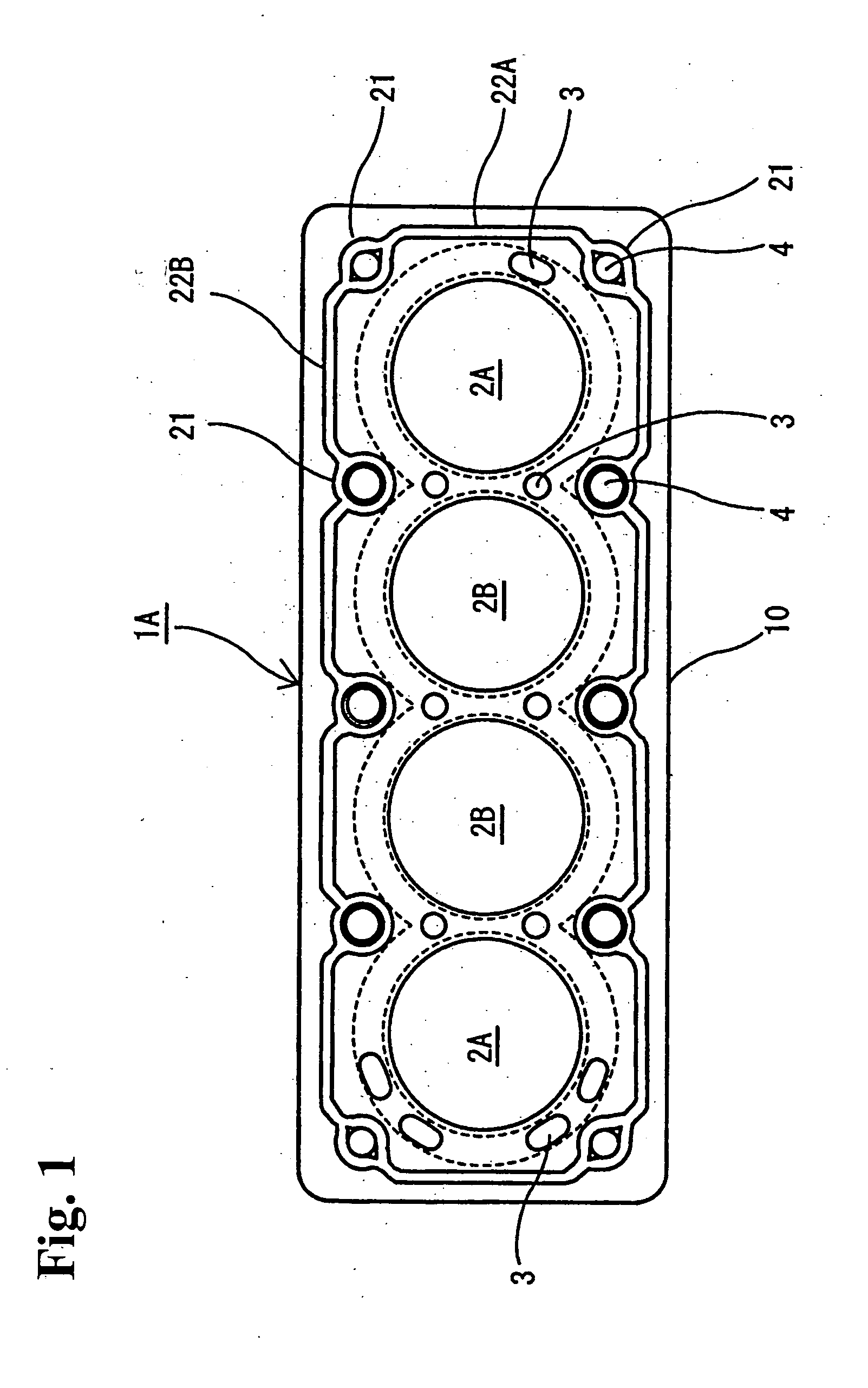
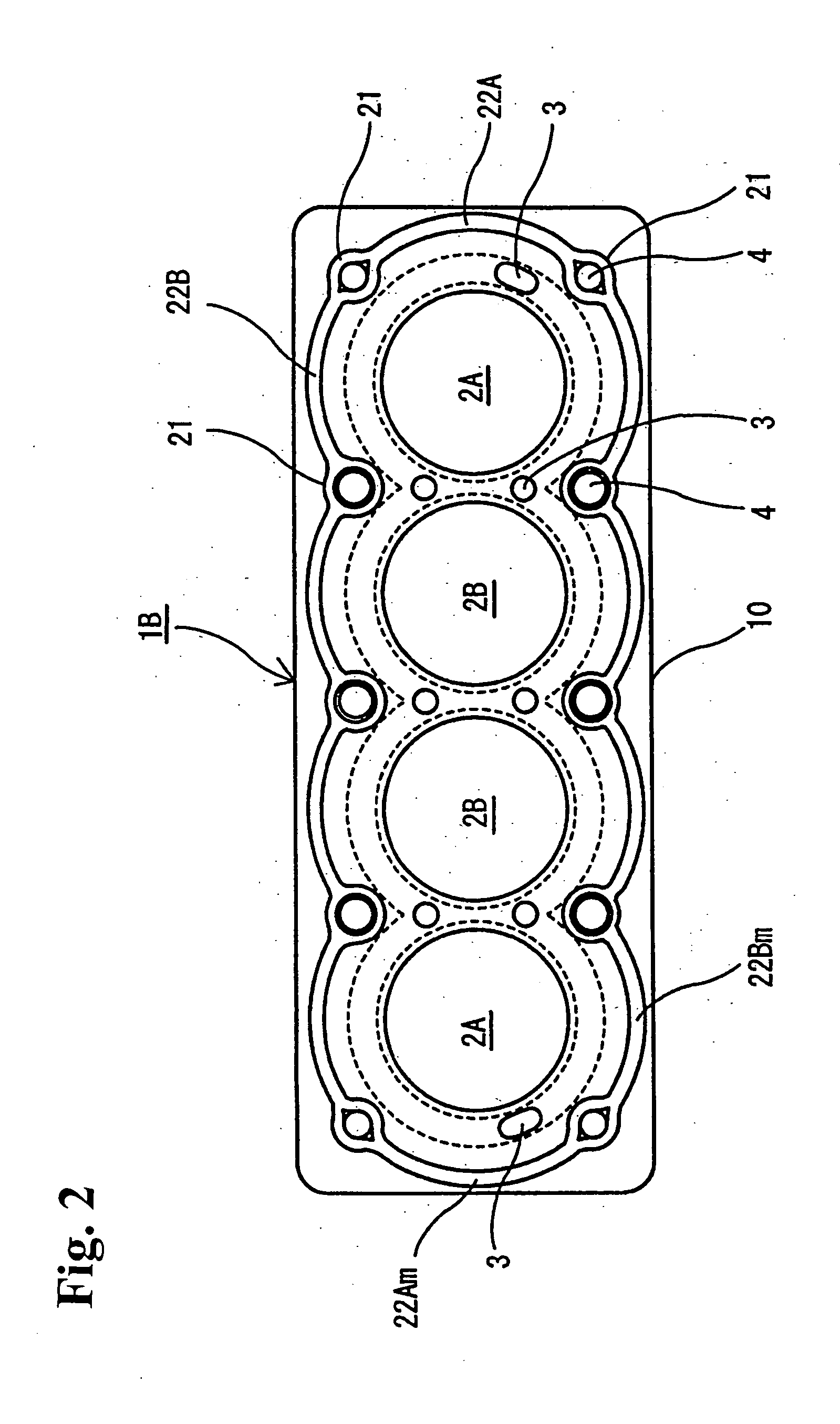
[0034] Hereinafter, embodiments of a cylinder head gasket of the present invention will be explained with reference to the drawings. In addition, FIGS. 1˜6 are type explanatory drawings, and structures are exaggeratingly shown by different sizes of cylinder bores and beads, dimensions of waved beads, and so on from actual sizes so that the structures are easily understood.

[0035] The cylinder head gasket according to the present invention is a metal gasket to be installed between engine members such as a cylinder head and a cylinder block (cylinder body) of an engine, to seal high-temperature and high-pressure combustion gas of cylinder bores, and fluid such as coolant water or oil and so on in coolant-water channels or coolant-oil channels and so on.

[0036] The cylinder head gasket is used for a multi-cylinder engine, and configured with a single or a plurality of metal plates (metal base plate) constituted by a mild steel plate, stainless annealing material (annealing material), a...


PUM


Abstract

A cylinder head gasket is formed by a metal plate, for constituting the gasket, having at least one cylinder hole and a plurality of bolt holes arranged to surround the at least one cylinder hole. Bolt-hole beads are formed in the metal plate to surround the respective bolt holes. Also, suppress adjusting beads are formed in the metal plate to be situated between adjacent bolt-hole beads.

Description

BACKGROUND OF THE INVENTION AND RELATED ART STATEMENT [0001] The present invention relates to a cylinder head gasket to be installed between two members, such as a cylinder head and a cylinder block of an engine, to seal therebetween. More specifically, the present invention relates to the cylinder head gasket being able to control the deformation of a cylinder bore. [0002] The cylinder head gasket is fastened by head bolts in a state of being installed between the cylinder head and cylinder block (cylinder body) of an auto engine and has the role of sealing a fluid such as combustion gas, oil, and coolant water. [0003] On the other hand, recently, with the improvement of fuel consumption and enhancement of antipollution measures, there is a tendency of miniaturization of the automobile engine. In a small engine, fuel efficiency is a focal point of engine development, wherein the improvement of the fuel consumption is enhanced by reducing the friction resistance between the piston r...

Claims


Application Information

Patent Timeline
IPC IPC(8): B60T11/236
CPCF16J15/0818F02F11/00F16J15/02F16J15/08
Inventor ISHIKAWA, SHINICHIROKINOSHITA, YUUICHI
Owner ISHIKAWA GASKET CO LTD
Why Eureka
Try Eureka