Semiconductor device provided with feedback circuit including resistive element and capacitive element

a feedback circuit and semiconductor technology, applied in the field of semiconductor devices, can solve problems such as oscillation of circuits and loss of phase margins, and achieve the effects of stabilizing an output voltage, improving the phase margin of an open loop, and increasing the response speed of output voltag

Active Publication Date: 2006-07-27
RENESAS ELECTRONICS CORP
View PDF11 Cites 29 Cited by
  • Summary
  • Abstract
  • Description
  • Claims
  • Application Information

AI Technical Summary

Benefits of technology

[0007] It is an object of the present invention to provide a semiconductor device capable of stabilizing an output voltage as well increasing a response speed of the output voltage by addition of a new feedback loop for improving a phase margin of an open loop as a whole of a switching power supply circuit.

Problems solved by technology

For this reason, there is a problem in that a phase of an open loop as a whole of the power supply circuit in a resonance frequency of the inductor and the capacitor changes by about 180°, which causes a phase margin to be lost, leading to oscillation of the circuit.

Method used


Image

  • Semiconductor device provided with feedback circuit including resistive element and capacitive element
  • Semiconductor device provided with feedback circuit including resistive element and capacitive element
  • Semiconductor device provided with feedback circuit including resistive element and capacitive element

Examples


first modification

[0058]FIG. 5 is a circuit diagram showing a configuration of a conventional switching power supply circuit. FIG. 6 is a circuit diagram showing a configuration of a switching power supply circuit according to a first modification of the present invention, corresponding to FIG. 5. FIGS. 5 and 6 each show a step-down synchronous rectification switching power supply circuit.

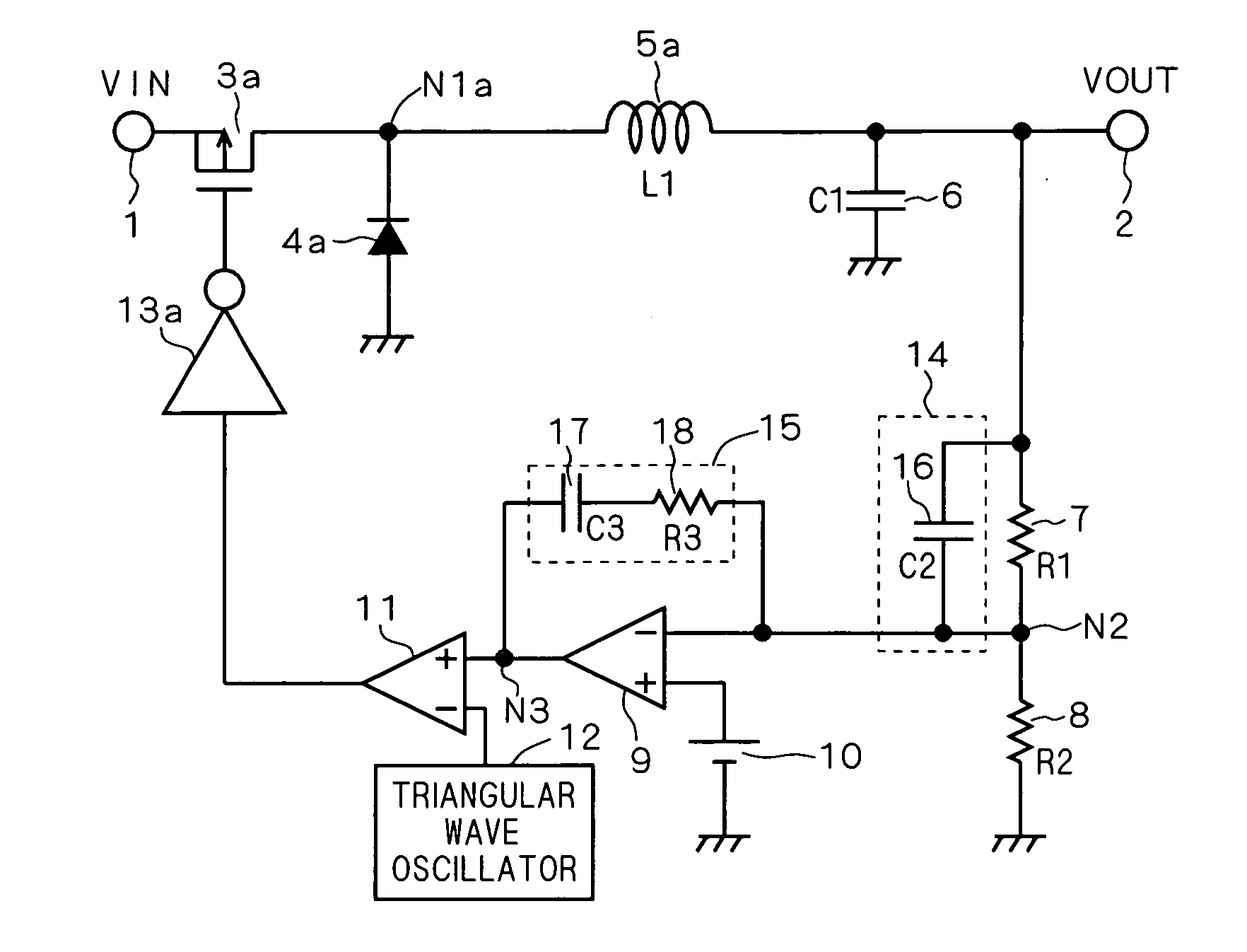
[0059] In the conventional switching power supply circuit shown in FIG. 5, an NMOS transistor 40a and a gate driver 41a are provided in place of the diode 4a in the conventional switching power supply circuit shown in FIG. 1. A gate electrode of the NMOS transistor 40a is connected to an output terminal of the gate driver 41a, a source electrode thereof is connected to a ground potential, and a drain electrode thereof is connected to a node N1a. An input terminal of the gate driver 41a is connected to an output terminal of the PWM comparator 11.

[0060] The switching power supply circuit according to the first modif...

second modification

[0061]FIG. 7 is a circuit diagram showing a configuration of a conventional switching power supply circuit. FIG. 8 is a circuit diagram showing a configuration of a switching power supply circuit according to a second modification of the present invention, corresponding to FIG. 7. FIGS. 7 and 8 each show a step-up diode rectification switching power supply circuit.

[0062] Referring to FIG. 7, the conventional step-up diode rectification switching power supply circuit includes an NMOS transistor 3b, a diode 4b, an inductor 5b, and a gate driver 13b. Similar to the conventional switching power supply circuit shown in FIG. 1, this conventional switching power supply circuit also includes an input terminal 1, an output terminal 2, capacitors 6, 16, 17, resistors 7, 8, 18, an error amplifier 9, a power supply 10, a PWM comparator 11, and a triangular wave oscillator 12.

[0063] The inductor 5b is connected between the input terminal 1 and a node N1b. A gate electrode of the NMOS transisto...

third modification

[0065]FIG. 9 is a circuit diagram showing a configuration of a conventional switching power supply circuit. FIG. 10 is a circuit diagram showing a configuration of a switching power supply circuit according to a third modification of the present invention, corresponding to FIG. 9. FIGS. 9 and 10 each show a step-up synchronous rectification switching power supply circuit.

[0066] In the conventional switching power supply circuit shown in FIG. 9, a PMOS transistor 40b and a gate driver 41b are provided in place of the diode 4b in the conventional switching power supply circuit shown in FIG. 7. A gate electrode of the PMOS transistor 40b is connected to an output terminal of the gate driver 41b, a source electrode thereof is connected to a node N1b, and a drain electrode thereof is connected to the output terminal 2. An input terminal of the gate driver 41b is connected to an output terminal of the PWM comparator 11.

[0067] The switching power supply circuit according to the third mod...


PUM


Abstract

The present invention provides a switching power supply circuit capable of stabilizing an output voltage as well as increasing a response speed of the output voltage by improving a phase margin of an open loop as a whole of the switching power supply circuit. The switching power supply circuit according to the present invention includes a resistor and a capacitor in addition to a configuration of a conventional switching power supply circuit. The resistor is connected between a node and the capacitor. The capacitor is connected between the resistor and another node. The resistor and the capacitor configure a phase compensation circuit. The phase compensation circuit has a cut-off frequency in accordance with a resonance frequency of an inductor and a capacitor by adjusting a resistance value of the resistor and a capacitance of the capacitor.

Description

BACKGROUND OF THE INVENTION [0001] 1. Field of the Invention [0002] The present invention relates to a semiconductor device. In particular, the present invention relates to a switching power supply circuit. [0003] 2. Description of the Background Art [0004] In a switching power supply circuit as one of semiconductor devices, an error between a voltage obtained by division of an output voltage by a serial resistive element and a predetermined reference voltage is amplified with an error amplifier. On the basis of the error, On-Duty of a switching element is controlled with a PWM (Pulse Width Modulator) comparator, to keep an output voltage value constant. Thus, it is possible to obtain a desired direct current voltage from an input direct current voltage. [0005] It is to be noted that conventional techniques regarding the switching power supply circuit are disclosed in, for example, Japanese Patent Application Laid-Open Nos. 2001-86740, 2003-52170 and 2004-80985. [0006] As thus descr...

Claims


Application Information

Patent Timeline
Patent Type & Authority Applications(United States)
IPC IPC(8): G05F1/40G05F1/618
CPCH02M3/156
Inventor HATA, TAKEHIROKUROIWA, TATSUOONISHI, EIJI
Owner RENESAS ELECTRONICS CORP
Why Eureka
Try Eureka