Atmospheric refractivity profiling apparatus and methods

a technology of atmospheric refractivity and profiling apparatus, applied in the direction of instruments, direction finders using radio waves, heat measurement, etc., can solve the problems of difficult characterization and/or prediction, short radio links such as those associated with cellular communications, and ducting of long-range radio communications

Inactive Publication Date: 2006-07-27
RADIOMETRICS CORP
View PDF8 Cites 41 Cited by
  • Summary
  • Abstract
  • Description
  • Claims
  • Application Information

AI Technical Summary

Benefits of technology

[0023] With these and other objects in view, which will become apparent to one skilled in the art as the description proceeds, this invention resides in the novel construction, combination, and arrangement of parts and method substantially as hereinafter described, and more particularly defined by the appended claims, it being understood that changes in the precise embodiment of the herein disclosed invention are meant to be included as come within the scope of the claims.

Problems solved by technology

Radio and / or optical propagation paths are influenced by atmospheric refractivity in a manner that is often difficult to characterize and / or predict.
Long range radio communications are also subject to ducting and other effects of refractivity, and short radio links such as those associated with cellular communications can also be affected.

Method used


Image

  • Atmospheric refractivity profiling apparatus and methods
  • Atmospheric refractivity profiling apparatus and methods
  • Atmospheric refractivity profiling apparatus and methods

Examples


Embodiment Construction

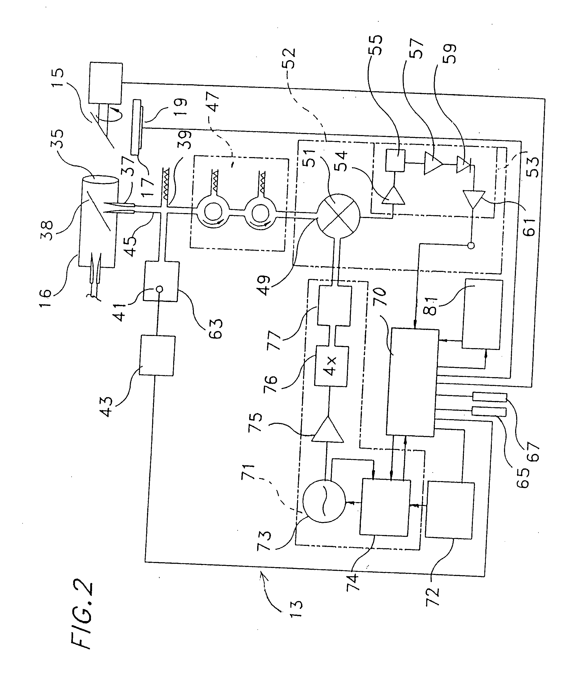
[0034] The Earth's atmosphere emits thermal radiation in all wavebands that consists of blackbody radiation from both atmospheric atomic and molecular constituents. This emitted thermal radiation is reabsorbed and re-emitted by these atomic and molecular species. The absorption spectrum of the clear atmosphere in the microwave signal region from 10 GHz to 200 GHz (at sea level) is shown in graphical form in FIG. 1. The prominent peaks in this spectral region are caused by absorption lines or, equivalently, emission lines, of atmospheric water vapor and oxygen. Regions of the spectrum between these peaks have lower signal absorption and therefore are called transmission windows. The downwelling radiation reaching the Earth is expressed as brightness temperature, the temperature of a blackbody emitting equivalent radiation, and can be written in a linearized equation as:

Tb=Tcosmice−T+(1−e−T)TMR

[0035] Where Tcosmic is the residual radiation from the Big Bang, tau is the atmospheric o...


PUM


Abstract

Apparatus and methods for characterizing atmospheric refractivity and its evolution in time and space utilizing passive radiation emission measurement devices are disclosed. Based on an instrument such as a passive microwave radiometer, ancillary meteorological measurements and other information and observations, the apparatus and methods provide useful signatures for characterizing atmospheric refractivity. The system can observe to any vector in the sky, giving directional as well as zenithal measurements of the refractivity profile, its spatial and temporal gradients, and the spatial and temporal trending of the profile and its gradients.

Description

FIELD OF THE INVENTION [0001] This invention relates to atmospheric profiling using passive microwave radiometry, and, more particularly, relates to such profiling for characterizing atmospheric refractivity and refractivity gradients. BACKGROUND OF THE INVENTION [0002] Radio and / or optical propagation paths are influenced by atmospheric refractivity in a manner that is often difficult to characterize and / or predict. Refractive gradients in the atmosphere due to the structure of temperature and water vapor fields can cause reflective layers that can duct or trap propagation. Optical mirages are the result of refractive gradients that cause upward bending thus precluding views of the surface at distances from the observer. Horizontal gradients in refractivity influence astronomical observations, celestial navigation, radar tracking of orbiting and other objects in flight, and other pointed observations. [0003] Such atmospheric effects can preclude or divert propagation such that sour...

Claims


Application Information

Patent Timeline
Patent Type & Authority Applications(United States)
IPC IPC(8): G01B9/00G01S3/02
CPCG01K11/006
Inventor SOLHEIM, FREDRICK S.WARE, RANDOLPH H.EXNER, MICHAEL L.
Owner RADIOMETRICS CORP
Why Eureka
Try Eureka