Circuit for detecting electric current

a circuit and current detection technology, applied in the direction of electric variable regulation, process and machine control, instruments, etc., can solve the problem of error in the peak value of load current detected by the diode and the capacitor, and achieve the effect of improving the accuracy of load current detection and heightening the reliability of products

Active Publication Date: 2006-07-27
KWON YONG JAI
View PDF3 Cites 35 Cited by
  • Summary
  • Abstract
  • Description
  • Claims
  • Application Information

AI Technical Summary

Benefits of technology

[0008] The present invention is disclosed to solve the aforementioned drawback and it is an object of the present invention to provide a circuit for detecting an electric current adapted to offset a change in current detection value in relation to an increase of backward leakage current caused by a temperature increase, thereby improving the accuracy of the load current detection and heightening the reliability of products.

Problems solved by technology

In other words, there is a drawback in that an error can occur in the peak value of the load current detected by the diode and the capacitor due to changes of the forward current (A′) flowing in the diode.

Method used


Image

  • Circuit for detecting electric current
  • Circuit for detecting electric current
  • Circuit for detecting electric current

Examples


first embodiment

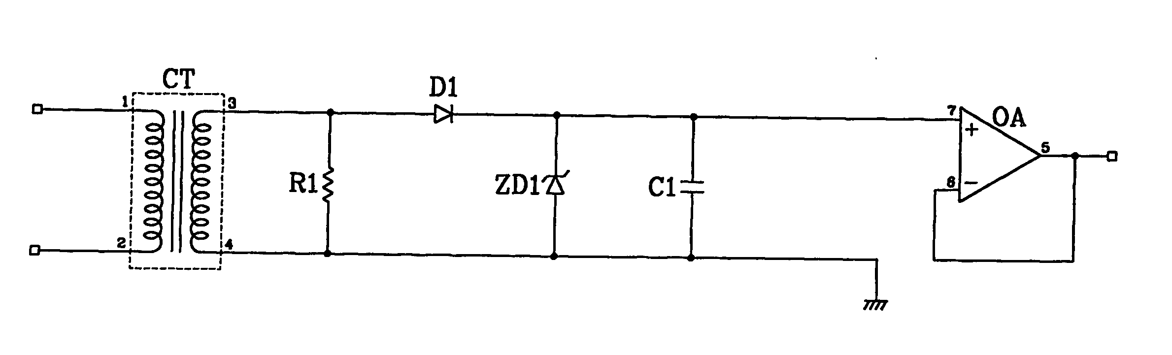
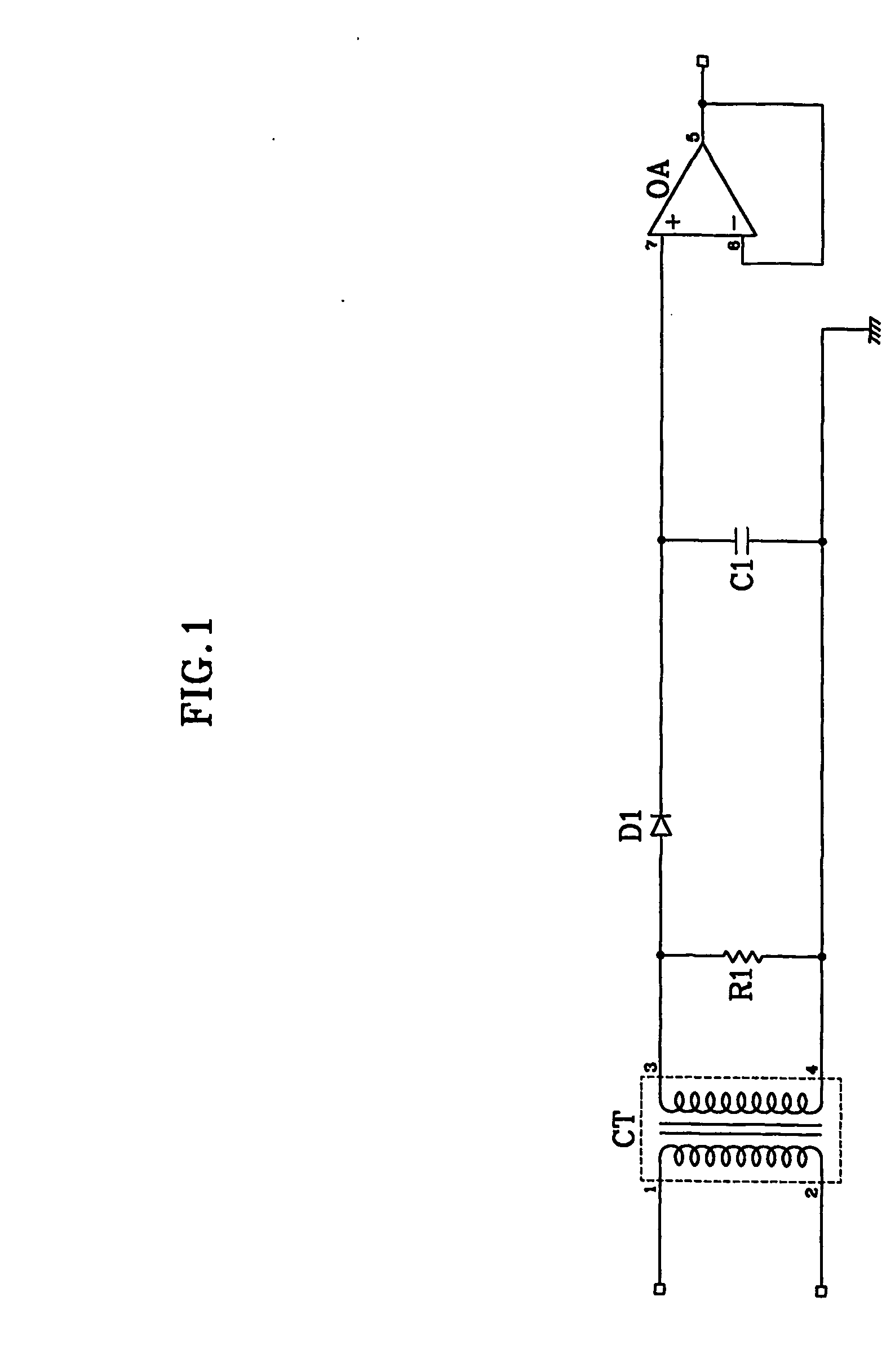
[0029]FIG. 3 is a schematic drawing for illustrating a current detecting circuit according to the first embodiment of the present invention, where the current detecting circuit includes a current transformer (CT), a resistor (R1), a diode (D1), a capacitor (C1), an operational amplifier (OA) and a zener diode (ZD1).

[0030] The current transformer (CT) receives a load current and transforms same to a small current that is easy for measurement and outputs same. The resistor (R1) is connected to both ends (3, 4) of a secondary winding of the current transformer (CT) in order to set up an output voltage at the secondary winding of the current transformer (CT).

[0031] An anode of the diode (D1) is connected to one end (3) of the secondary winding of the current transformer (CT) and a cathode of the diode (D1) is connected to a non-inversion terminal (7) of the operational amplifier (OA). One end of the capacitor (C1) is connected to a cathode of the diode (D1) and the other end of the ca...

second embodiment

[0043]FIG. 5 illustrates a current detecting circuit according to the second embodiment of the present invention, where the circuit includes a current transformer (CT), a resistor (R1), a diode (D1), a capacitor (C1), an operational amplifier (OA) and a shunt resistor (R2).

[0044] The current transformer (CT) receives a load current, transforms same to a small current that is easy for measurement and outputs same. The resistor (R1) is connected to both ends (3, 4) of a secondary winding of the current transformer in order to set up an output voltage at the secondary winding of the current transformer.

[0045] An anode of the diode (D1) is connected to one end (3) of the secondary winding of the current transformer and a cathode of the diode (D1) is connected to a non-inversion terminal (7) of the operational amplifier (OA). One end of the capacitor (C1) is connected to a cathode of the diode (D1) and the other end of the capacitor (C1) is grounded.

[0046] The non-inversion terminal o...

third embodiment

[0060]FIG. 7 illustrates a current detecting circuit according to the third embodiment of the present invention, where the circuit includes a current transformer (CT), a resistor (R1), a diode (D1), a capacitor (C1), an operational amplifier (OA), zener diode (ZD1) and a shunt resistor (R2).

[0061] The current transformer (CT) receives a load current and transforms same to a small current that is easy for measurement and outputs same. The resistor (R1) is connected to both ends (3, 4) of a secondary winding of the current transformer in order to set up an output voltage at the secondary winding of the current transformer.

[0062] An anode of the diode (D1) is connected to one end (3) of the secondary winding of the current transformer and a cathode of the diode (D1) is connected to a non-inversion terminal (7) of the operational amplifier (OA). One end of the capacitor (C1) is connected to a cathode of the diode (D1) and the other end of the capacitor (C1) is grounded.

[0063] The non...


PUM


Abstract

A circuit for detecting an electric current by which a loss portion of a forward current caused by a backward leakage current of a diode generated by the influence of temperature increase can be compensated such that error in the peak value of a load current detected by surrounding high temperature can be minimized, and credibility reliability can be increased for electric instruments that call for an accurate control of the load current and that generate a high temperature such as induction heating cookers, induction heaters and the like.

Description

CROSS REFERENCE TO RELATED APPLICATIONS [0001] This application is a U.S. continuation application filed under 35 U.S.C. §111(a) claiming benefit under 35 U.S.C. §§120 and 365(c) of International Application No. PCT / KR2004 / 001426, filed on Jun. 15, 2004, which claims benefit of priority from Korean patent application No. 10-2003-0038949, filed on Jun. 16, 2003. The entire contents of the foregoing two applications are hereby incorporated by reference.FIELD OF THE INVENTION [0002] The present invention relates to a circuit for detecting an electric current and, more particularly, to a circuit for detecting an electric current adapted to compensate a leakage current of a diode sensitive to temperature changes to improve accuracy and minimize errors. BACKGROUND OF THE INVENTION [0003] As is well known, an increasingly accepted trend of late for electric and electronic gadgets is a requirement for a more accurate load current control in controlling operations thereof. In order to discri...

Claims


Application Information

Patent Timeline
Patent Type & Authority Applications(United States)
IPC IPC(8): G01R31/08G01R19/04G01R19/15G05F1/567H05B6/04
CPCG01R19/04G05F1/567H05B6/04G01R19/15
Inventor KWON, YONG JAI
Owner KWON YONG JAI
Why Eureka
Try Eureka