Multi-display configuration method
a configuration method and multi-display technology, applied in two-way working systems, instruments, computing, etc., can solve the problems of not being able to convert received content from a stream, it is unrealistic to realize a multi-display screen of an ultra-large size (say, several hundred inches) with a single portable display,
- Summary
- Abstract
- Description
- Claims
- Application Information
AI Technical Summary
Problems solved by technology
Method used
Image
Examples
first embodiment
[0034] A first embodiment in which one image data is reconfigured and displayed on four displays using a multi-display adaptor is explained below.
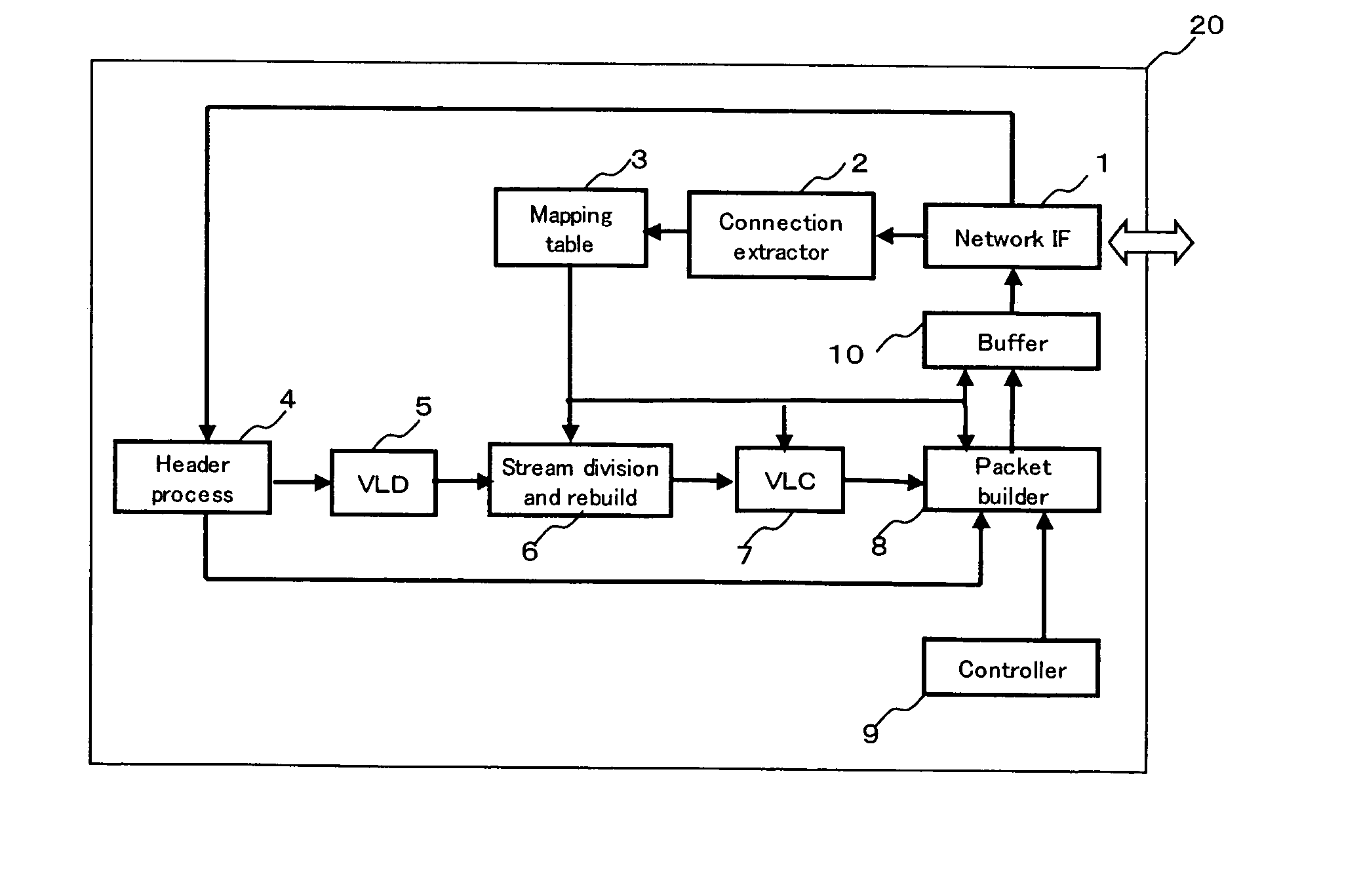
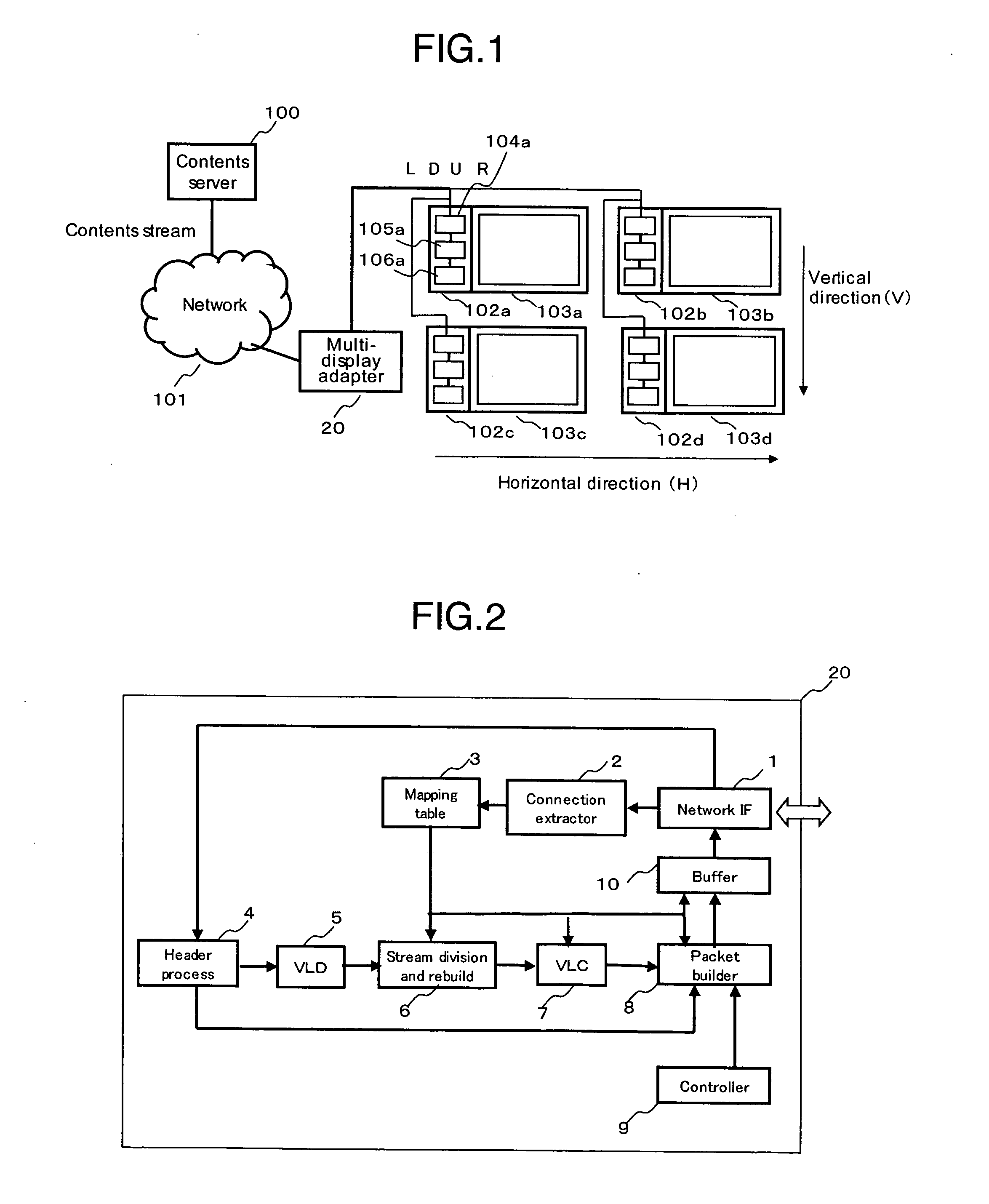
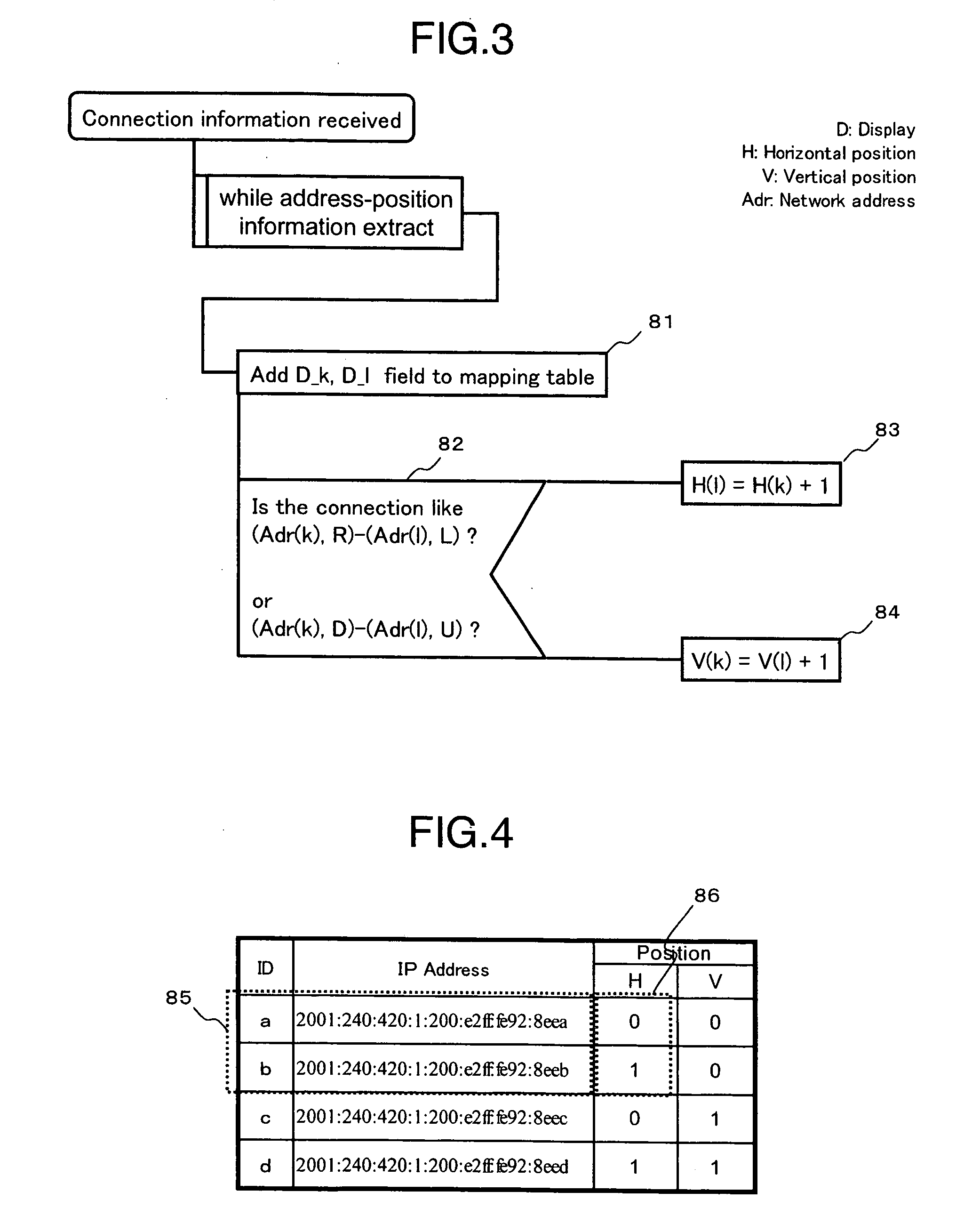
[0035]FIG. 1 is a diagram showing a content distribution system used with the multi-display adaptor according to this embodiment. Reference numeral 100 designates a content server to transmit various content including images and music as a streaming data to the network 101. The content data transmitted from the content server 100 are received by a multi-display adaptor 20 temporarily, and after being reconfigured, transmitted to the displays 103a to 103d as an IP packet. The display 103a, in addition to a screen unit having a display screen for displaying the content, includes a network connection unit 102a. The network connection unit 102a is configured of a network interface 104a, a memory 106a for storing the control software to control the transmission and receiving of packets, and a processor 105a for executing the software. The disp...
second embodiment
[0061] The first embodiment concerns an example of realization of a multi-display adaptor as a hardware using various exclusive chips. The second embodiment, on the other hand, realizes the same function in software. The multi-display adaptor according to this embodiment is also assumed to be arranged in the same network as in FIG. 1.
[0062]FIG. 9 shows a hardware configuration of the multi-display adaptor according to this embodiment. A communication interface 31 for conducting communication with the network, a CPU (Central Processing Unit) 32 for performing the arithmetic operation, a memory 33 for storing the internal data, etc., an interface for connecting an external storage unit 34 and the external storage unit 34, an interface 35 for connecting external input devices such as a mouse and a keyboard, and a display interface 36 for connecting a display device, etc. are interconnected through a bus 37. The content stream is input through the communication interface 31 and process...
third embodiment
[0063] In the first and second embodiments, the network is connected by wire. The third embodiment, however, uses a radio network such as wireless LAN. The configuration of the multi-display adaptor according to this embodiment is similar to the configuration explained in the first or second embodiment. In the first and second embodiments, the connection can be determined from the physical position of the network port of the display. In the case where the network is configured of wireless LAN, however, the network connection is established in the range covered by the radio wave. Therefore, the connection between the displays is unknown, and the connection is required to be recognized by another means.
[0064] In FIG. 10, a switch 107a indicating the installed display position is added to indicate the horizontal and vertical positions. The switch 107 is an ordinary dip switch or a rotary switch set for horizontal and vertical positions.
[0065] By notifying as an option of the neighbor...
PUM
 Abstract
Description
Claims
Application Information
 - R&D
- Intellectual Property
- Life Sciences
- Materials
- Tech Scout
- Unparalleled Data Quality
- Higher Quality Content
- 60% Fewer Hallucinations
Browse by: Latest US Patents, China's latest patents, Technical Efficacy Thesaurus, Application Domain, Technology Topic, Popular Technical Reports.
© 2025 PatSnap. All rights reserved.Legal|Privacy policy|Modern Slavery Act Transparency Statement|Sitemap|About US| Contact US: help@patsnap.com


