Image processing device and image capturing device

Inactive Publication Date: 2006-07-27
BROTHER KOGYO KK
View PDF8 Cites 36 Cited by
  • Summary
  • Abstract
  • Description
  • Claims
  • Application Information

AI Technical Summary

Benefits of technology

[0017] With the above configuration, the in-plane angle of the subject is determined based on the plane image which is obtained by use of the three-dimensional shape of the subject. Therefore, the in-plane angle of the subject can be determined more precisely compared to cases where the rotation angle of the document is deter

Problems solved by technology

However, the conventional image processing device described above executes the following complicated process as image analysis necessary for the conversion into the image in which the captured document rotated to the erect direction is viewed from the front.
In this case, the image processing takes a long time with a heavy workload of image analysis for the line bundle recognition, etc., and thus the image processing device is required hig

Method used


Image

  • Image processing device and image capturing device
  • Image processing device and image capturing device
  • Image processing device and image capturing device

Examples


first embodiment

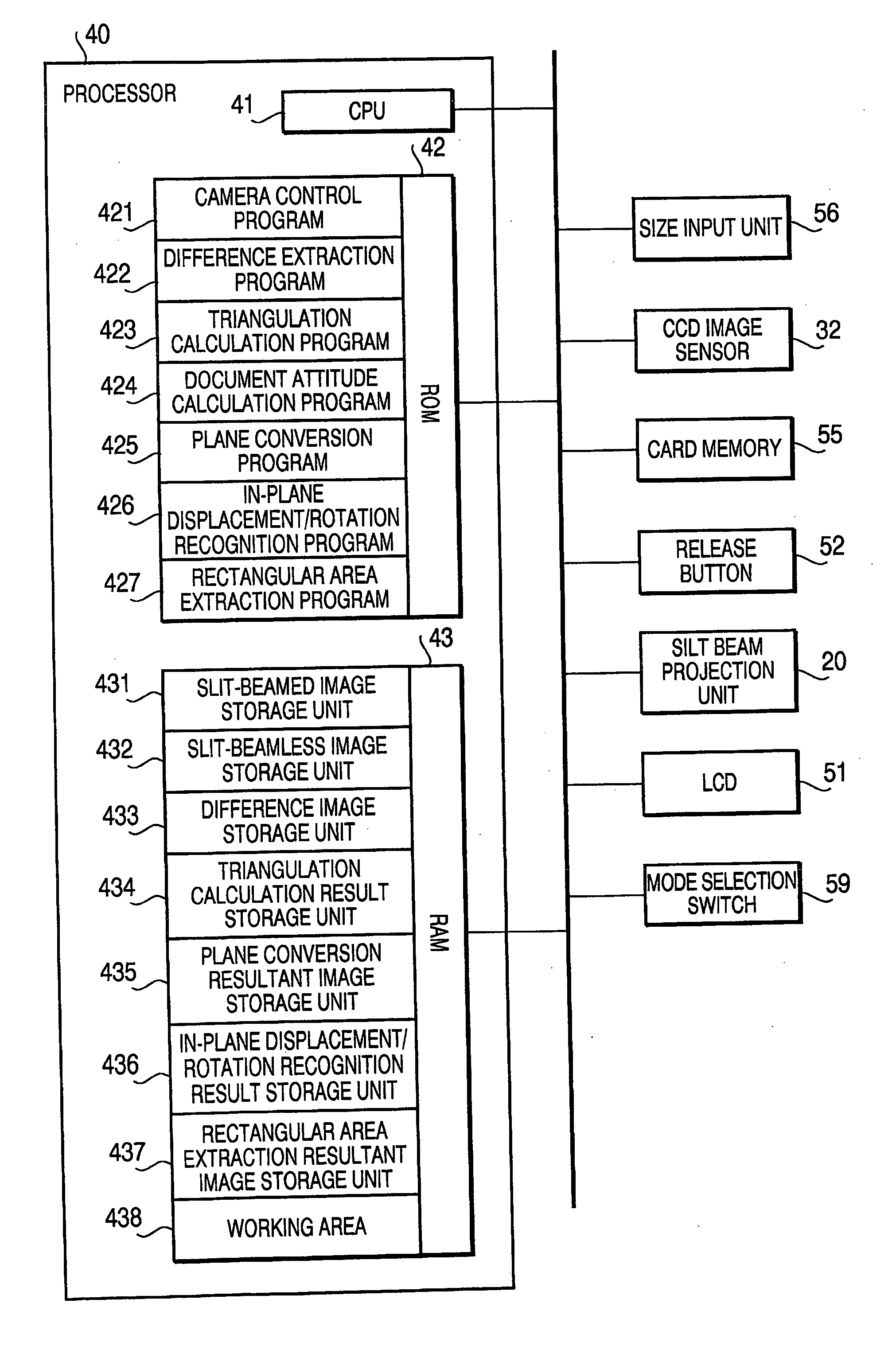
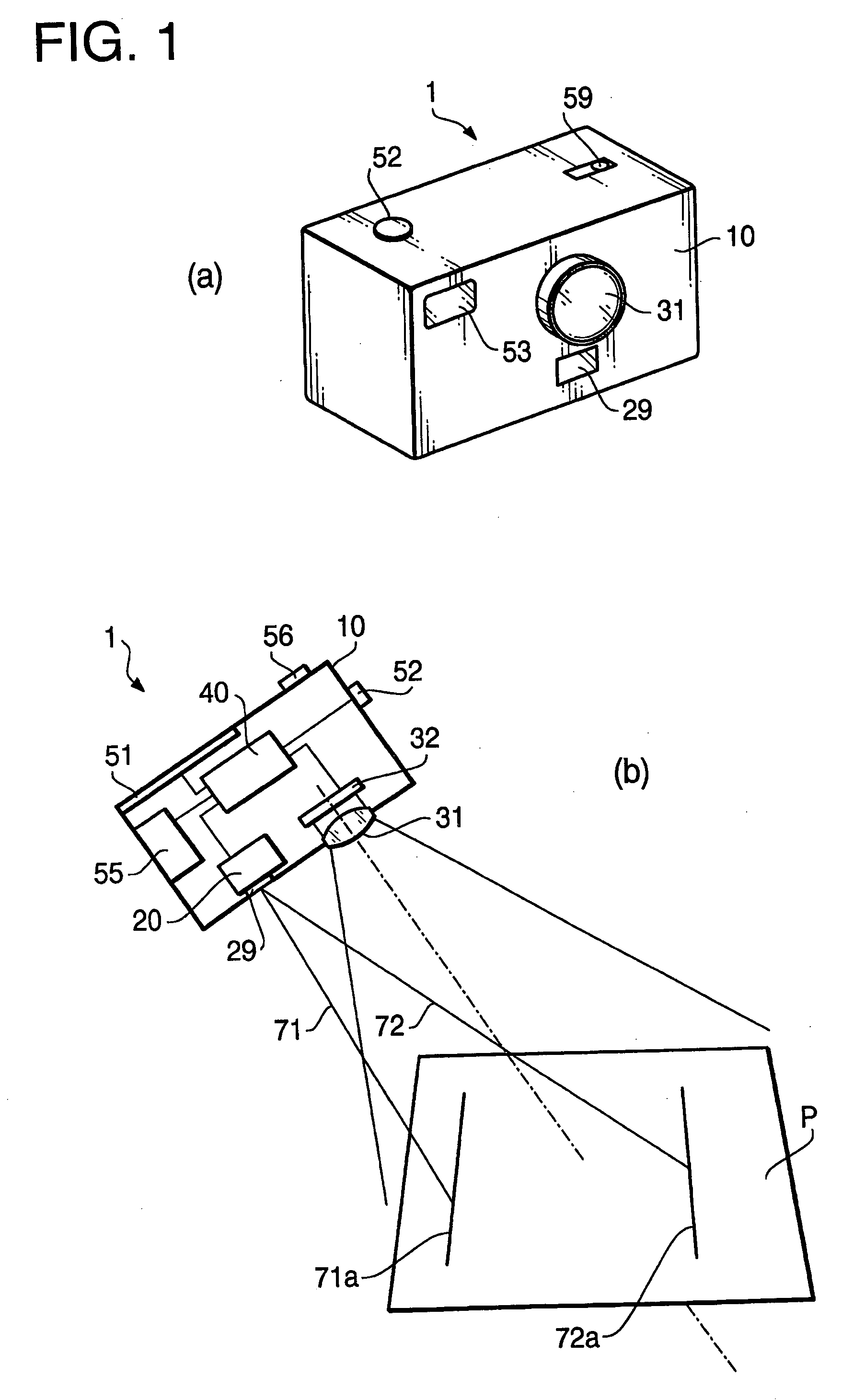
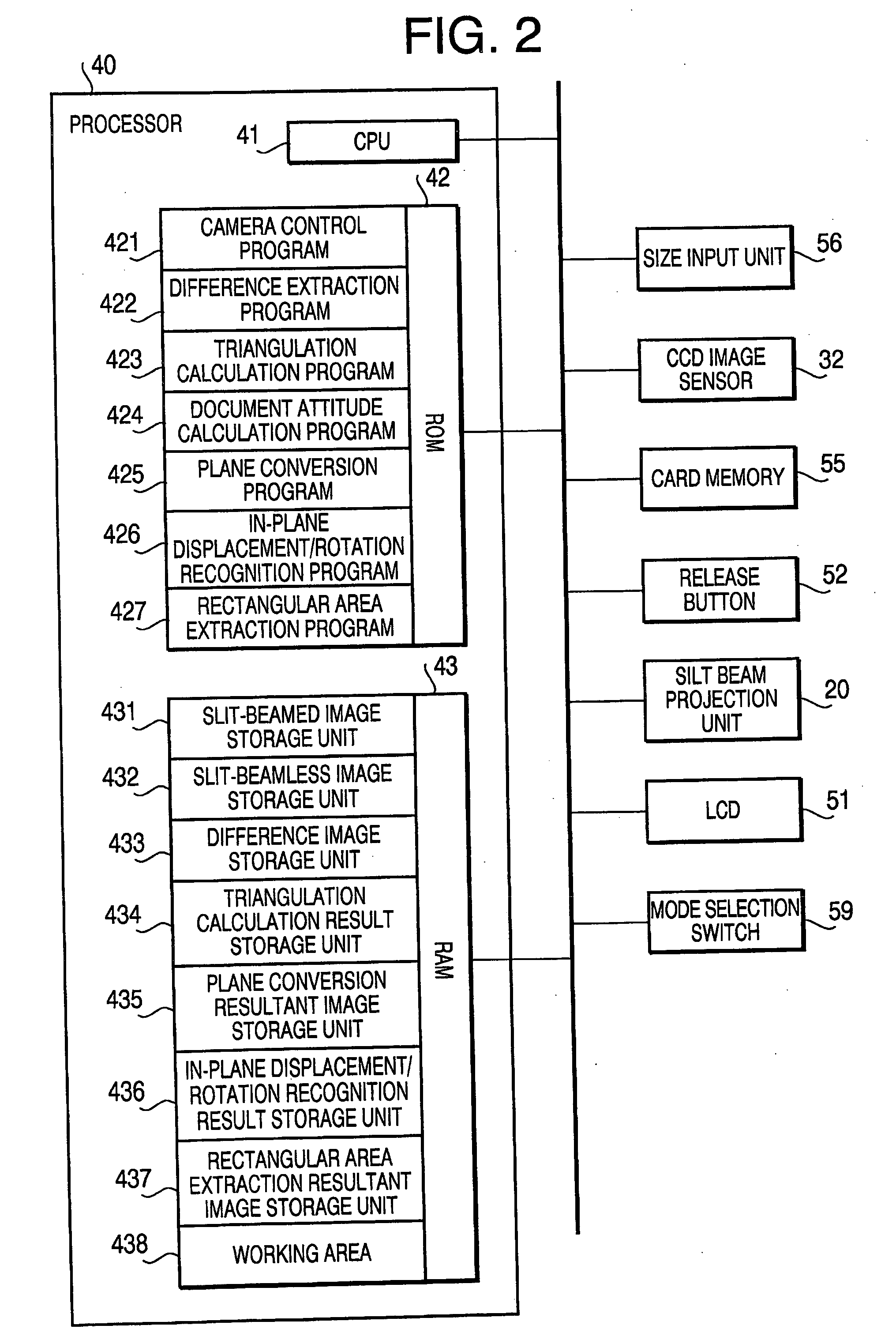
[0101]FIG. 1(a) is an overall perspective view of an image capturing device 1 in accordance with a first embodiment of the present invention. FIG. 1(b) is a schematic sectional view of the image capturing device 1. FIG. 2 is a block diagram showing the composition of a control system of the image capturing device 1.

[0102] As shown in FIG. 1, the image capturing device 1 includes a body case 10 in a box shape, an imaging lens 31 provided at the front of the body case 10, a CCD image sensor 32 placed at the rear of the imaging lens 31 (inside the image capturing device 1) and a slit beam projection unit 20 placed underneath the imaging lens 31. The image capturing device 1 further includes a processor 40 installed in the body case 10, a release button 52 and a mode selection switch 59 placed on top of the body case 10, a card memory 55 inserted in the body case 10, and a size input unit 56 provided on the back of the body case 10. The above components of the image capturing device 1 ...

second embodiment

[0211] In the following, a second embodiment in accordance with the present invention will be described. Since images are converted according to a preset program in the conventional image conversion technique (described in Japanese Patent Provisional Publication No. 2002-334327), even if the image obtained by the conversion is an image exactly planned by the program, it has been impossible for some users to edit the image according to the user's requests (enlarging and extracting a particular part of a document, etc.). The second embodiment is configured to be also capable of resolving such a problem. By the second embodiment described below, an image capturing device, capable of automatically converting an image of a subject shot from an oblique direction into an image of the subject shot from the front and thereafter editing the image into an image according to the user's intention, is realized.

[0212] In figures regarding the second embodiment which will be explained below, the s...

third embodiment

[0278] In the following, an image capturing device 100 in accordance with a third embodiment of the present invention will be described. The image capturing device 100 of the third embodiment has a configuration equivalent to that of the image capturing device 1B of the second embodiment except for some characteristic parts which will be explained below. In the following explanation, the characteristic parts of the image capturing device 100 of the third embodiment in contrast with the image capturing device 1B of the second embodiment will be described one by one.

[0279] The image capturing device 1B of the second embodiment described above was configured to edit the plane image displayed on the LCD 51 according to the operations to the operation button 57 in the editing process (S2107) in FIG. 24. Instead of the operation button 57, the image capturing device 100 of the third embodiment is equipped with detection means which detects movement of the body case 10 in the three-dimens...


PUM


Abstract

An image processing device comprises: plane conversion means which receives a subject image in which a subject having a particular shape has been captured and shape information about three-dimensional shape of the subject from the outside and converts the subject image into a plane image in which the subject is viewed from a prescribed direction based on the shape information; and in-plane position detection means which recognizes a subject area in the plane image as an area representing the subject and determines a position of the subject in the plane image.

Description

TECHNICAL FIELD [0001] The present invention relates to an image processing device which converts an inputted image into an image in which a subject captured in the inputted image is viewed from a different viewpoint, and an image capturing device employing the image processing device. BACKGROUND OF THE INVENTION [0002] In order to record the contents of a document with ease, without using a device like a scanner, portable image capturing devices like digital cameras are sometimes used for capturing and recording an image of such a document. When a document is shot for such a purpose, it is ideal that the document be shot right from the front so that characters on the document will not be captured to be obscure or unreadable. However, there are cases where a person shooting a document can not stand up (during a meeting, etc.) and has to shoot the document on a desk from an oblique direction. [0003] Japanese Patent Provisional Publication No. 2002-334327 (hereinafter referred to as a...

Claims


Application Information

Patent Timeline
IPC IPC(8): H04N5/262G06T3/00G09G5/37H04N1/387H04N5/232
CPCG06T3/00H04N1/387H04N5/232H04N23/631
Inventor SUZUKI, HIROAKIIWASAKI, TAKEO
Owner BROTHER KOGYO KK
Why Eureka
Try Eureka