Discharge lamp lighting device and illiminator

a technology of lighting device and discharge lamp, which is applied in lighting and heating apparatus, casings/cabinets/drawers, electrical apparatus casings/cabinets/drawers details, etc., can solve the problems of inability to simply make the side walls b>122/b> thicker, and the difficulty of downsizing the discharge lamp lighting apparatus, etc. the effect of reducing the manufacturing cost of the lighting system

Inactive Publication Date: 2006-07-27
MATSUSHITA ELECTRIC WORKS LTD
View PDF2 Cites 6 Cited by
  • Summary
  • Abstract
  • Description
  • Claims
  • Application Information

AI Technical Summary

Benefits of technology

[0013] In this way, the lighting system is configured with using the discharge lamp lighting apparatus that the manufacturing cost thereof is reduced, so that the manufacturing cost of the lighting system can be reduced, too.

Problems solved by technology

It, however, is necessary to provide a clearance between the housing and a printed circuit board or to provide an insulator between them for assuring the insulation between the housing and the printed circuit board on which a discharge lamp lighting circuit is mounted, and thereby, it is difficult to downsize the discharge lamp lighting apparatus.
However, when the side walls 122 are made thicker, it may cause the occurrence of shrinkage cavity or welding in molding, so that the method for simply making the side walls 122 thicker cannot be adopted.
Therefore, mechanical strength of the core is lower than that of the other portion of the die, and the core may be replaced frequently, so that the life of the die becomes shorter.
As a result, it causes the increase of the costs of the discharge lamp lighting apparatus and the lighting system using the same.

Method used


Image

  • Discharge lamp lighting device and illiminator
  • Discharge lamp lighting device and illiminator
  • Discharge lamp lighting device and illiminator

Examples


first embodiment

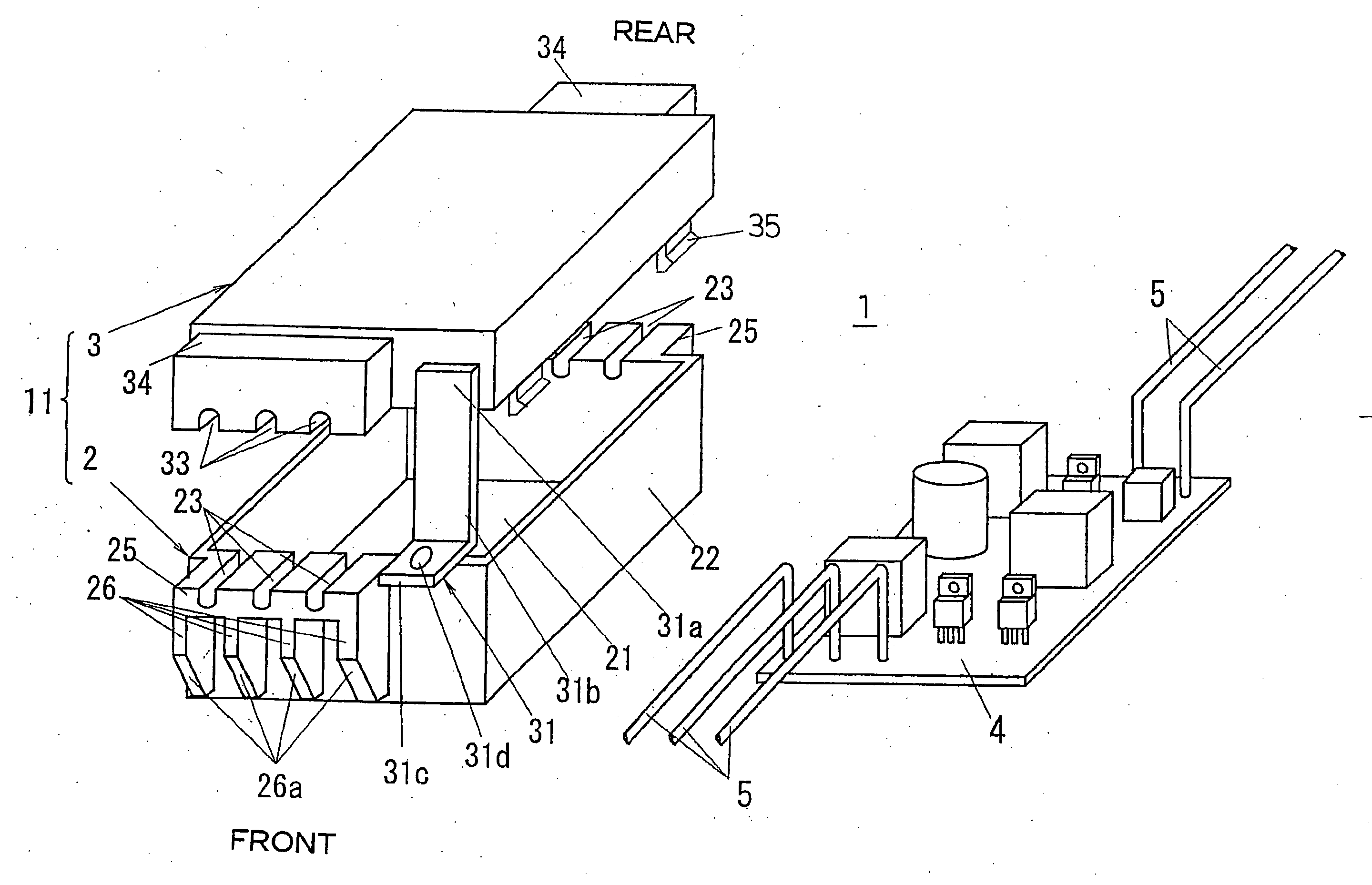
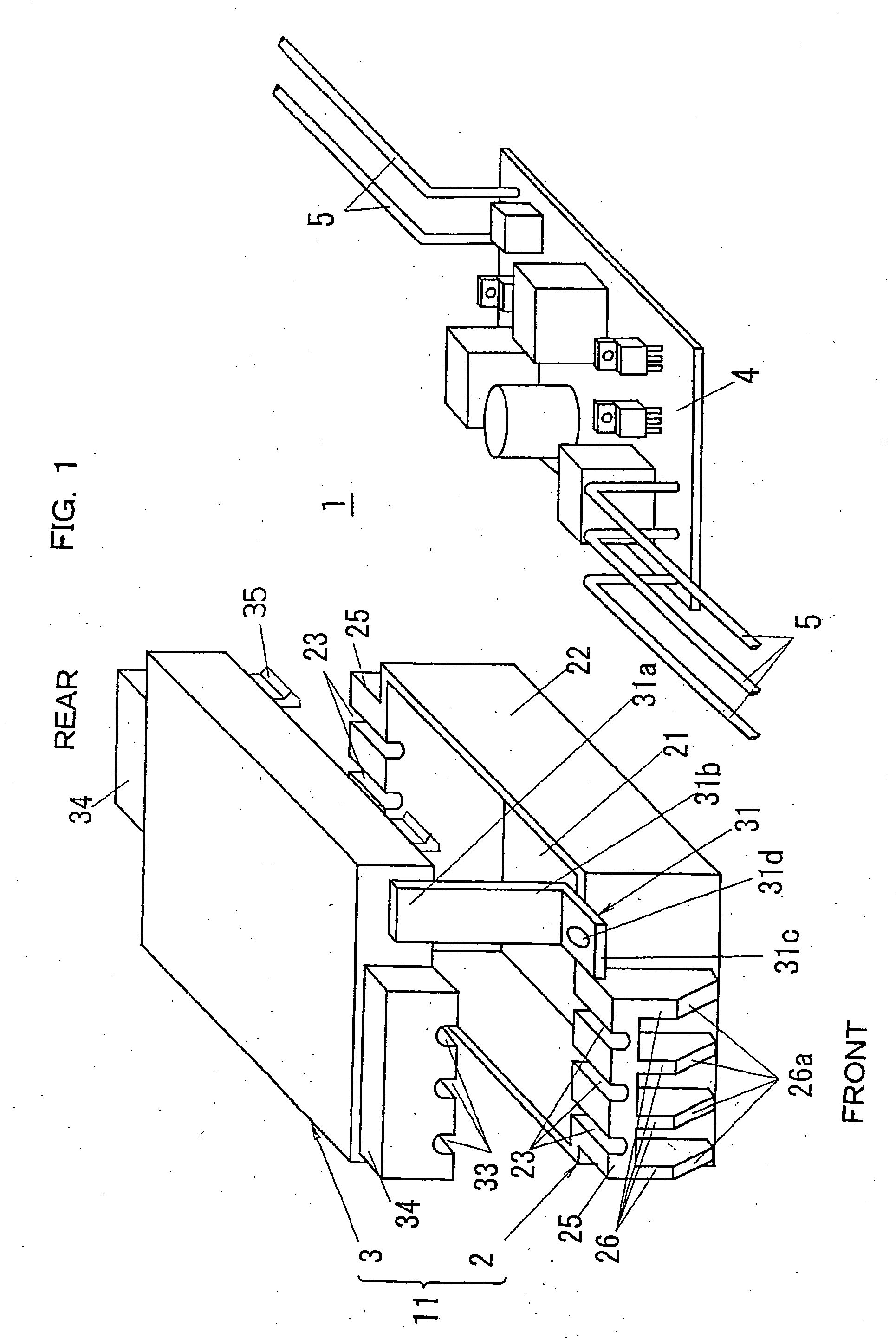
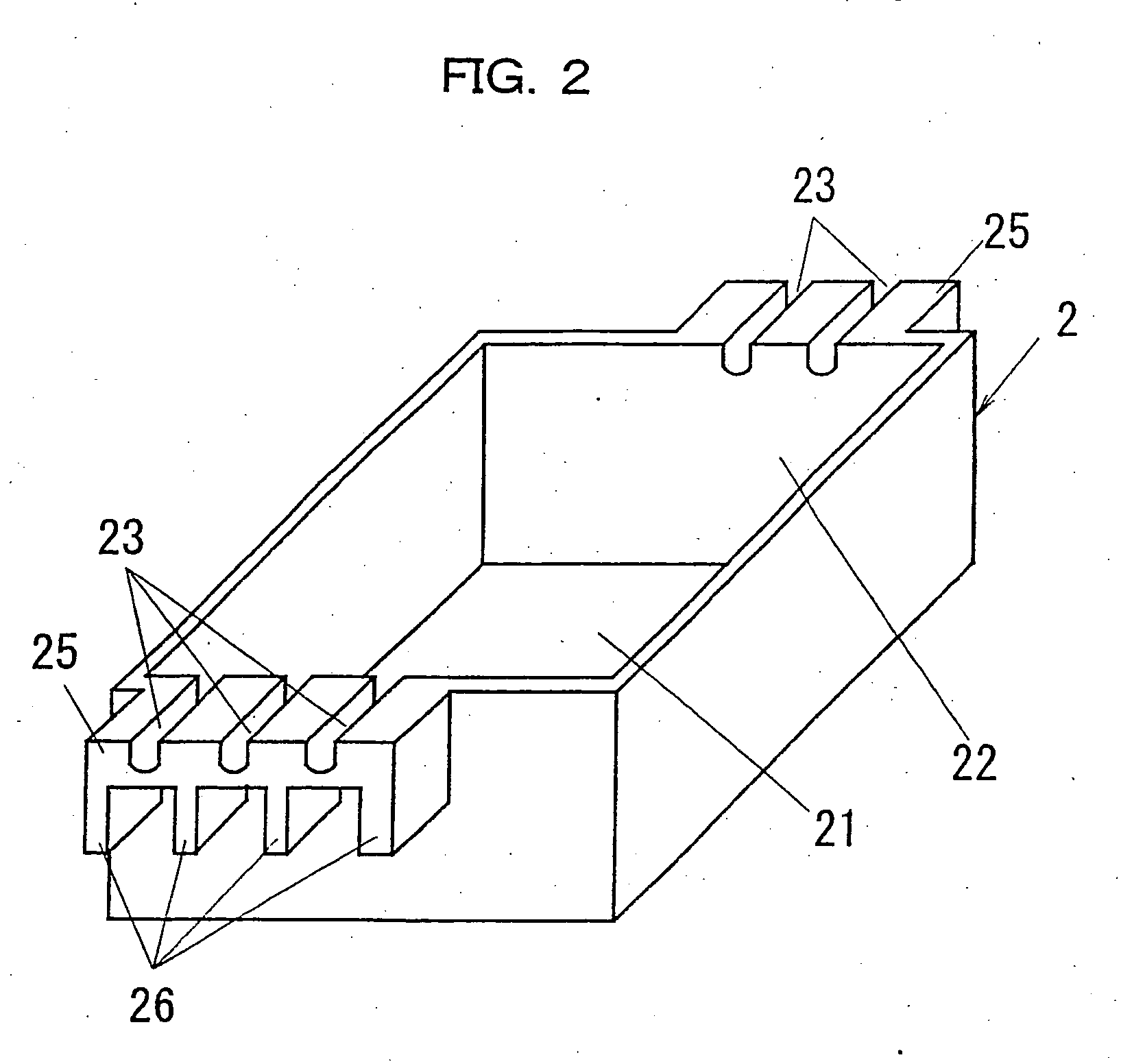
[0027] A first embodiment of the present invention is described. FIG. 1 is an exploded perspective view showing a configuration of a discharge lamp lighting apparatus in a first embodiment. A housing 11 of the discharge lamp lighting apparatus 1 is formed as a rectangular solid shape which is longer in cross direction similar to the conventional discharge lamp lighting apparatus 100 shown in FIG. 10 and FIG. 11. As shown in FIG. 1, the housing 11 is comprised of a base member 2 which is formed as a tubular box shape and has a rectangular bottom plate 21 and side walls 22 set up along entire circumference of an upper face of the bottom plate 21, and a cover member 3 for closing an upper opening of the base member 2. A printed circuit board 4, on which a discharge lamp lighting circuit is mounted, is contained in an inside of the base member 2.

[0028] As shown in FIG. 1, protruding portions 25 are formed on a front face and a rear face of the side walls 22 of the base member 2 for pro...

second embodiment

[0039] Subsequently, a second embodiment of the present invention is described. FIG. 8 is an exploded perspective view showing a configuration of a discharge lamp lighting apparatus in the second embodiment. As shown in FIG. 8, the discharge lamp lighting apparatus 1 of the second embodiment is configured that the housing 11 is covered by a metal cover 6 comprised of a first cover piece 61 and a second cover piece 62. The fixing portions 31 are not formed on the cover member 3. Other configurations are substantially the same as those in the above first embodiment.

[0040] The first cover piece 61 is configured to be a rectangular solid top face of which is opened so as to cover the base member 2. The second cover piece 62 is configured to be a rectangular solid bottom face of which is opened so as to cover the cover member 3. Hooking portions 61a, which are protruded upward and front ends of which are inwardly bent, are respectively provided on an upper edge of a front face and an up...

third embodiment

[0044] Subsequently, a third embodiment of the present invention is described. FIG. 9 shows a lighting system using the discharge lamp lighting apparatus in accordance with the present invention. As shown in FIG. 9, the lighting system 70 in accordance with the third embodiment is comprised of a main body 71 into which the discharge lamp lighting apparatus 1 in accordance with the first or second embodiment is contained, a lighting body 72 having a socket (not illustrated) to which a discharge lamp 75 is attached, an arm 73 which is coupled to the main body 71 and holds the lighting body 72 rotatable with respect to the main body 71, a discharge lamp cover 74 coupled with the lighting body 72 and having a reflector for distributing light of the discharge lamp 75, and so on.

[0045] By such a configuration, since the discharge lamp lighting apparatus that the manufacturing cost thereof is reduced is used, the manufacturing cost of the lighting system itself can be reduced.


PUM


Abstract

In a discharge lamp lighting apparatus for lighting a lighting system using a discharge lamp, a housing used for containing a printed circuit board on which a discharge lamp lighting circuit is mounted is formed by resin molding. In order to put out wires connected to the printed circuit board from an inside to outside of the housing, protruding portions are protruded outward from upper end portions of a front face and a rear face of side walls of a base member which constitute the housing, and wire putting grooves are formed on upper faces of the protruding portions. Furthermore, reinforcing ribs are provided for coupling the protruding portions and portions of the side walls except the protruding portions so as to reinforce mechanical strength of the protruding portions by the reinforcing ribs.

Description

TECHNICAL FIELD [0001] The present invention relates to a discharge lamp lighting apparatus and a lighting system using the same. BACKGROUND ART [0002] As for a housing of a discharge lamp lighting apparatus, a metal housing has been used, conventionally. It, however, is necessary to provide a clearance between the housing and a printed circuit board or to provide an insulator between them for assuring the insulation between the housing and the printed circuit board on which a discharge lamp lighting circuit is mounted, and thereby, it is difficult to downsize the discharge lamp lighting apparatus. In recent years, it is required to downsize the discharge lamp lighting apparatus and a lighting system using the same, so that a housing made of a synthetic resin, which requires no insulation between the housing and the printed circuit board and enables to downsize and to reduce the manufacturing cost, is used. [0003] An example of a discharge lamp lighting apparatus using a housing of ...

Claims


Application Information

Patent Timeline
Patent Type & Authority Applications(United States)
IPC IPC(8): F21V15/00F21V23/00F21V23/02F21Y103/00H05B41/02H05K5/00H05K5/02H05K7/00
CPCH05B41/02H05K5/0013H05K5/0247
Inventor GORIKI, TAKESHIKISHIMOTO, AKIHIROFUKUDA, KENICHI
Owner MATSUSHITA ELECTRIC WORKS LTD
Why Eureka
Try Eureka