Control device for vehicular drive system
- Summary
- Abstract
- Description
- Claims
- Application Information
AI Technical Summary
Benefits of technology
Problems solved by technology
Method used
Image
Examples
embodiment 1
[0105] Referring to the drawings, there will be described in detail the preferred embodiments of the present invention.
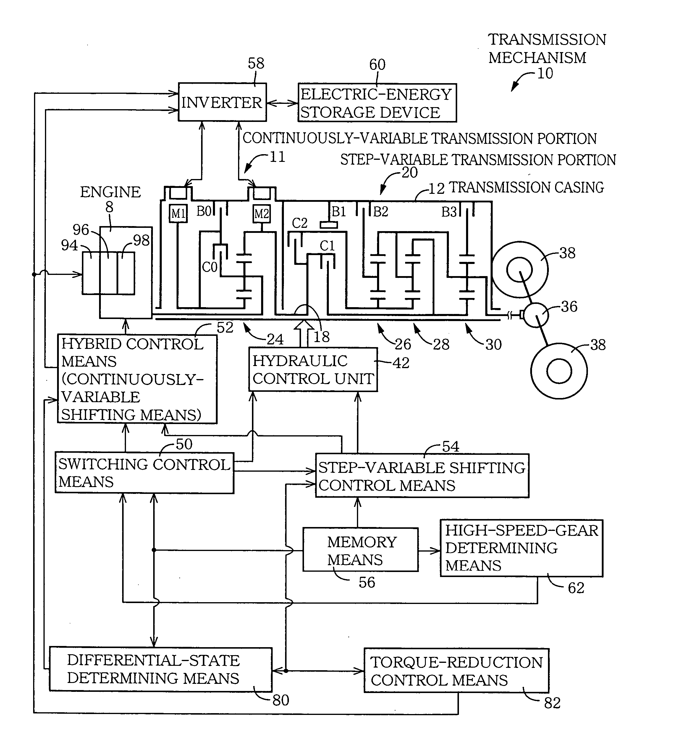
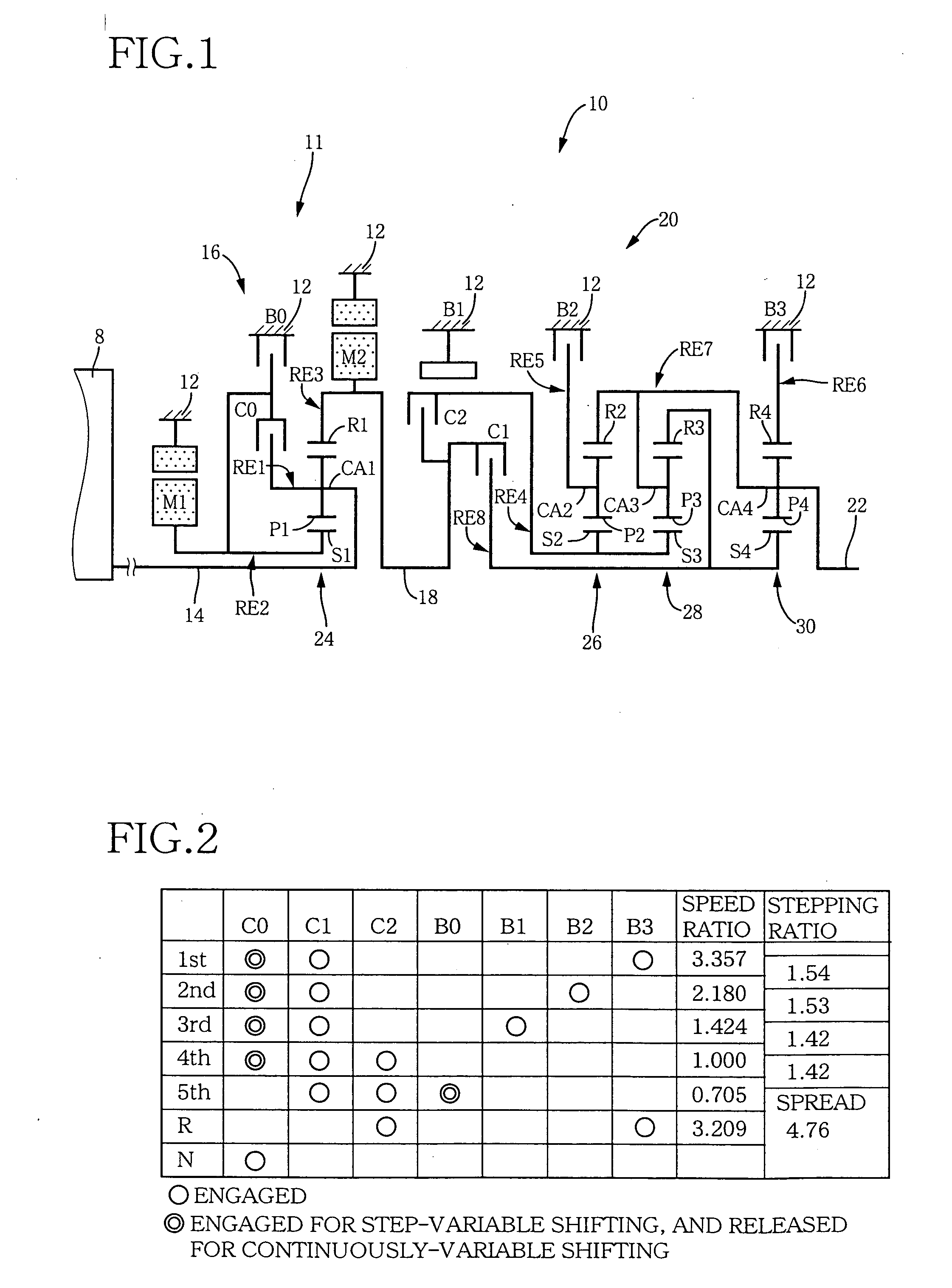
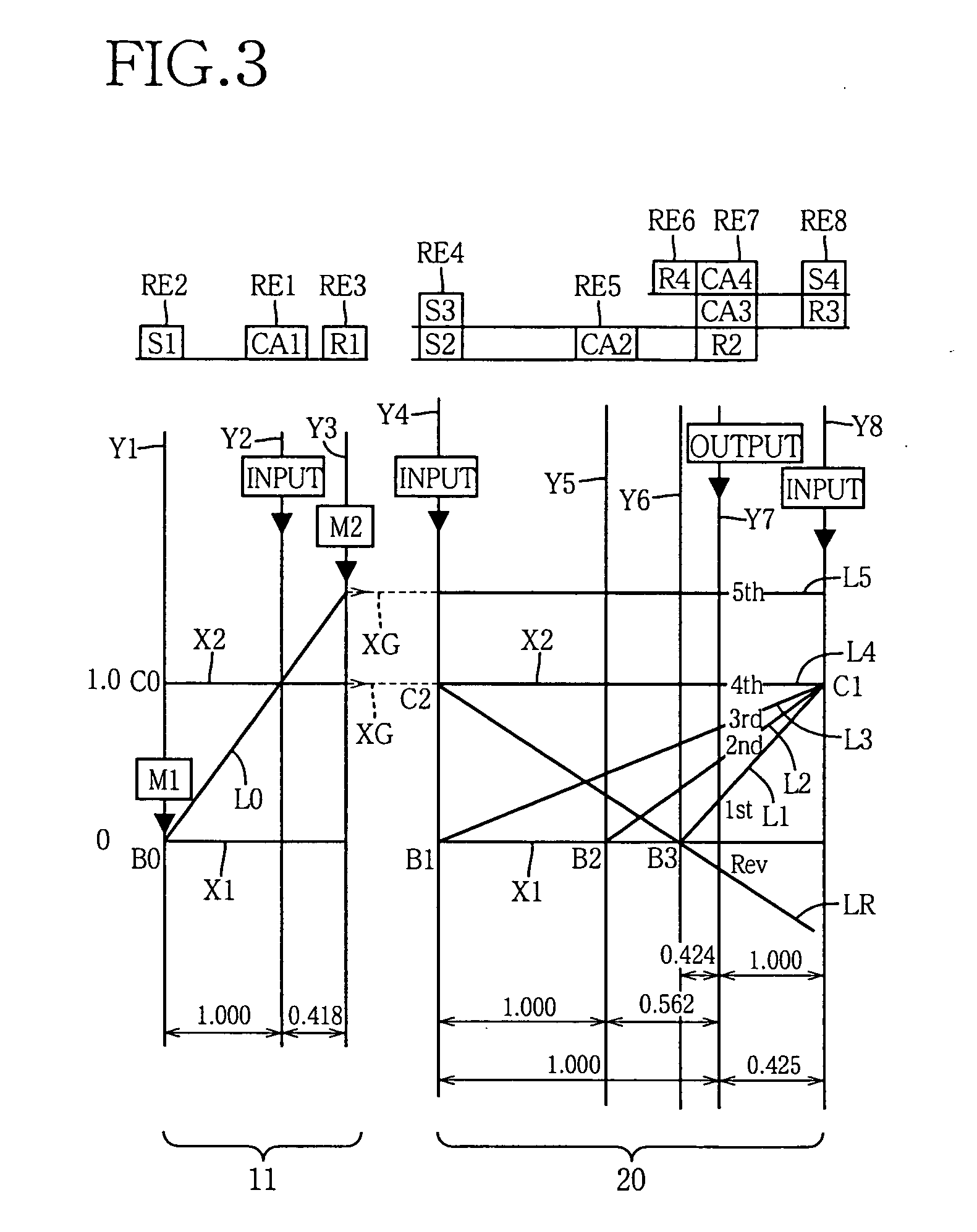
[0106]FIG. 1 is a schematic view explaining a transmission mechanism 10 constituting a part of a drive system for a hybrid vehicle, which drive system is controlled by a control device according to one embodiment of this invention. In FIG. 1, the transmission mechanism 10 includes: an input rotary member in the form of an input shaft 14 disposed on a common axis in a transmission casing 12 functioning as a stationary member attached to a body of the vehicle; a continuously-variable transmission portion 11 connected to the input shaft 14 either directly, or indirectly via a pulsation absorbing damper (vibration damping device) not shown; a step-variable or multiple-step transmission portion 20 disposed between the continuously-variable transmission portion 11 and drive wheels 38 (shown in FIG. 5) of the vehicle, and connected in series via a power transmitting membe...
embodiment 2
[0186] In the preceding embodiment, the hybrid control means 52 is arranged to implement the shifting control of the continuously-variable transmission portion 11 in synchronization with the shifting control of the step-variable transmission portion 20, that is, in the inertial phase in the process of the shifting action of the transmission portion 20, so that the total speed ratio γT of the transmission mechanism 10 is continuously changed before and after the shifting action of the step-variable transmission portion 20. The present embodiment provides some examples clarifying the shifting control of the continuously-variable transmission portion 11 which takes place in the inertial phase in the process of the shifting action of the step-variable transmission portion 20, for assuring a continuous change of the total speed ratio γT of the transmission mechanism 10 before and after the shifting action of the transmission portion 20.
[0187] In the preceding embodiment, the shifting co...
embodiment 3
[0215] Referring to the schematic view of FIG. 19, there is shown an arrangement of a transmission mechanism 70 in another embodiment of this invention, and FIG. 20 a table indicating a relationship between the gear positions of the transmission mechanism 70 and different combinations of engaged states of the hydraulically operated frictional coupling devices for respectively establishing those gear positions, while FIG. 21 is a collinear chart for explaining a shifting operation of the transmission mechanism 70.
[0216] The transmission mechanism 70 includes the continuously-variable transmission portion 11 having the first electric motor M1, power distributing mechanism 16 and second electric motor M2, as in the preceding embodiments. The transmission mechanism 70 further includes a step-variable transmission portion 72 having three forward drive positions. The transmission portion 72 is disposed between the continuously-variable transmission portion 11 and the output shaft 22 and ...
PUM
 Abstract
Description
Claims
Application Information
 - R&D
- Intellectual Property
- Life Sciences
- Materials
- Tech Scout
- Unparalleled Data Quality
- Higher Quality Content
- 60% Fewer Hallucinations
Browse by: Latest US Patents, China's latest patents, Technical Efficacy Thesaurus, Application Domain, Technology Topic, Popular Technical Reports.
© 2025 PatSnap. All rights reserved.Legal|Privacy policy|Modern Slavery Act Transparency Statement|Sitemap|About US| Contact US: help@patsnap.com


