
Intraocular lens inserter system components

a technology of inserter system and push rod, which is applied in the field of ophthalmic devices, can solve the problems of deteriorating vision, affecting the ocular lens acclimatization, and patients given glasses to wear, and achieve the effect of preventing damage to the iol

Inactive Publication Date: 2006-07-27
DUSEK VACLAV
View PDF25 Cites 138 Cited by
  • Summary
  • Abstract
  • Description
  • Claims
  • Application Information

AI Technical Summary

Benefits of technology

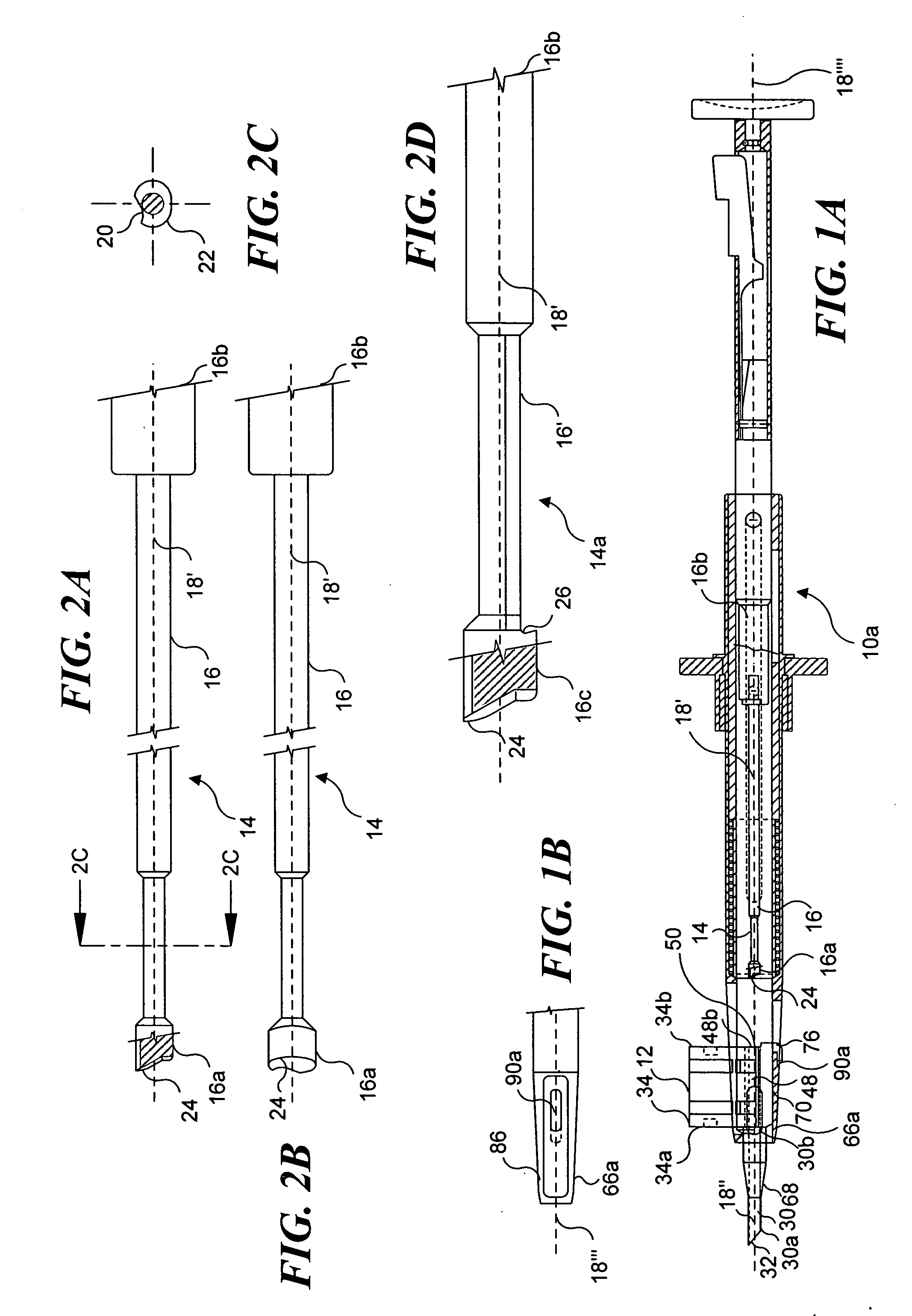
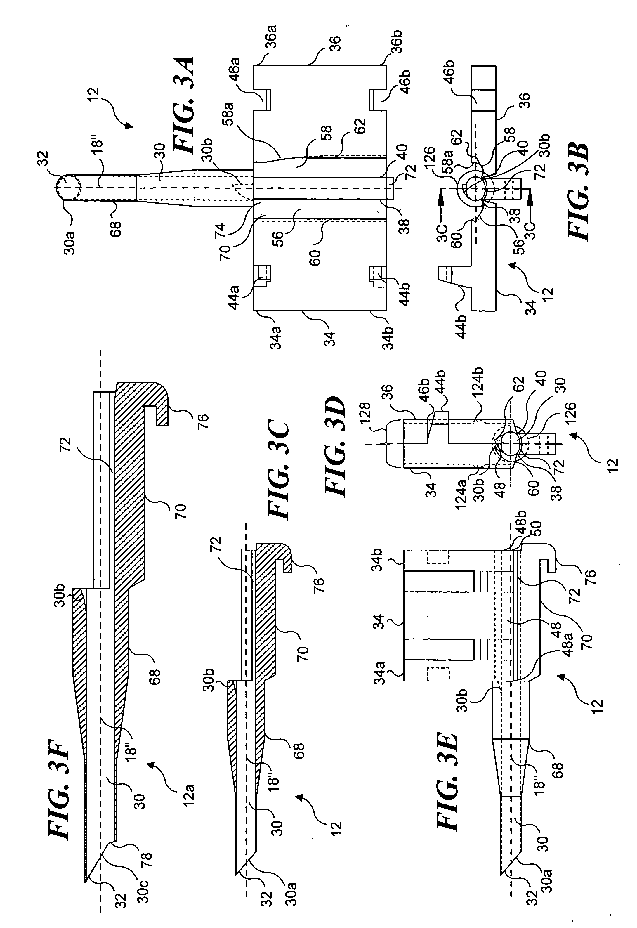
[0013] Accordingly, one aspect of the present invention is directed towards an IOL push rod that is configured for use with an IOL inserter and employed to controllably advance an IOL disposed inside an IOL cartridge along a longitudinal axis of the IOL cartridge. The intraocular lens push rod has a proximal end against which a force is applied to advance an IOL along the longitudinal axis. The disposable push rod comprises a material that is sufficiently rigid so that the push rod does not buckle when applying the force to advance the IOL. The push rod also includes a distal end (a push rod tip) contoured to contact a substantial portion of a perimeter of a proximal end of an IOL disposed inside an IOL cartridge. The contour of the distal end of the push rod is shaped to substantially correspond to a proximal end of a folded IOL. Thus, contact with a substantial portion of a perimeter of the proximal end of an IOL by the contoured leading edge of the distal end ensures that a force is more evenly applied by the push rod to advance an IOL along the longitudinal axis of an IOL cartridge, preventing damage to the IOL. A notch is optionally provided disposed adjacent to the distal end. The notch is sized to engage a haptic of an IOL between the notch and a recess formed on a distal end of an IOL cartridge, to enable an IOL to be maneuvered inside a lens capsule of a patient's eye.
[0019] All four of the embodiments of the cartridge housing are configured to enclose at least a portion of the cartridge and include a distal end, a proximal end, a top portion and a base portion, a cartridge receiving opening, a push rod opening, and a groove. The cartridge receiving opening is disposed proximate to the distal end of the housing and is adapted to receive at least the distal portion of the cartridge. This opening engages the cartridge within the housing in a first position and enables movement of the cartridge within the housing to a second position to secure the cartridge within the housing. The push rod opening is disposed proximate to the proximal end of the housing and is adapted to receive an IOL push rod.
[0021] The other three embodiments of the cartridge housing are attachable to an inserter and include a first opening and a second opening. In addition, the cartridge receiver opening is configured so that the first flange and the second flange are free to rotate about the first hinge and the second hinge, respectively. The first opening is disposed on the housing between the top portion and the base portion, and the second opening is disposed opposite the first opening, such that a stabilizer inserted into the first opening and the second opening is disposed substantially perpendicular to the longitudinal axis of the cartridge to prevent movement of the intraocular cartridge towards the base portion of the housing. These three embodiments of the cartridge housing also include a first protrusion and a second protrusion disposed between the top portion and the base portion of the housing. The first protrusion and the second protrusion are configured to respectively engage a first notch and a second notch included on the cartridge and to align the longitudinal axis of the cartridge with the longitudinal axis of an intraocular lens inserter such that an intraocular lens is readily advanced from the cartridge and into an eye. Also, a portion of the cartridge housing disposed between the top portion and the base portion is in sliding contact with the first flange and the second flange of the cartridge.
[0022] In the second embodiment of the cartridge housing, a distal portion of the IOL cartridge is inserted into the housing before the first flange and second flange are rotated toward each other. In this embodiment, after the first flange and the second flange are rotated toward and into contact with each other, the cartridge receiving opening enables movement of the IOL cartridge between the top portion and the base portion to seat the IOL cartridge within the housing.
[0023] In the third embodiment of the cartridge housing, the IOL cartridge is attached to the housing and pivotal within the cartridge receiving opening, from an initial position in which the first flange and the second flange are not yet rotated toward and into contact with each other, to a seated position within the cartridge receiving opening, which is attained after the first flange and the second flange have been rotated toward and into contact with each other. In the seated position, the IOL cartridge is securely locked in the position and the IOL is readily advanced from the IOL cartridge and into a patient's eye.
[0027] Yet another aspect of the present invention is directed towards a method for folding an IOL disposed in an IOL cartridge into a folded state in which one side of the IOL overlaps an opposite side, as the IOL is advanced through the IOL cartridge and into an eye. With an IOL disposed between opposite flanges that are rotatable toward each other about two spaced apart hinges, the two flanges are rotated toward each other, causing the one side and the opposite side of the IOL that is initially unfolded, to be folded toward each other and forming a bore through which the IOL can be advanced after being thus folded. The bore is tapered into an asymmetrical shape, wherein a contour of a curvature of one side of the bore becomes increasingly closer in matching a final shape of the bore at the distal end of the bore. Another step includes using the push rod to force the lens that is folded distally down the bore. As the lens advances, the tapered and asymmetrical shape of the distal end of the bore forces said one side of the lens to be folded into the bore. And further distally down the bore, a tapered and asymmetrical shape of the other side of the bore forces the other side of the lens to increasingly overlap the first side of the lens as the IOL moves distally through the bore toward its distal end.

Problems solved by technology

Cataracts occur when the normally clear lens of the eye becomes clouded, causing vision to deteriorate, because the clouding of the lens diffuses light and thus prevents the light from being properly focused on the retina.
Patients were given glasses to wear after this surgery, and they often encountered problems acclimating to the thick lenses required in the glasses.
The limited amount of support for the flexible IOL with the first and second members in the unfolded position does not enable the unfolded IOL to be retained unfolded in this position.
It is undesirable to store the flexible IOL in a folded state, since it may be damaged if not stored in essentially flat state.
However, when the load chamber is closed with the IOL folded therein, these ribs project inwardly into the first lumen, thus partially obstructing the first lumen so that movement of the IOL through the first lumen and into the patient's eye can be impaired.
Also, the ribs can damage the haptics (very small diameter wires that extend outwardly in an arc from opposite sides of the IOL to center it within the lens capsule) of the IOL, as the IOL travels through the first lumen.
As a result of the ribs partially obstructing the lumen, the push rod must be made smaller than the lumen, which limits the contact possible with the perimeter of the IOL by the push rod, because the push rod must pass the ribs when advancing the IOL through the lumen.
Thus, the diameter of a conventional push rod in an IOL inserter is too small to make much more than a point contact with the perimeter of the IOL.
Due to its small diameter, the push rod may move past the IOL without contacting its perimeter and thereby fail to advance the IOL as the push rod is moved through the lumen of the load chamber.
Furthermore, when the IOL is advanced through the lumen of the load chamber and into an eye, the push rod and the injection tube do not cooperate in any manner to enable maneuverability of the IOL in the eye.
Similarly, the single hinge joining the hinges does not enable a substantial portion of the unfolded IOL to be supported in a relatively flat position.
However, the haptic might still be damaged as the IOL is moved distally through the bore, if the attached haptic interacts with the push rod as the haptic is unlooped from the peg while being advanced by the push rod.

Method used


Image

  • Intraocular lens inserter system components
  • Intraocular lens inserter system components
  • Intraocular lens inserter system components

Examples


second embodiment

of Cartridge Housing

[0092]FIGS. 5A, 5B, 5C, and 5D illustrate the second of four preferred embodiments of yet another component of the present invention, a cartridge housing that is attached to the distal end of an IOL inserter, as shown in FIGS. 8B, and 8C and as shown prior to attachment in the exploded view of FIG. 8A.

[0093] As illustrated in FIG. 5A, cartridge housing 66b includes a distal end 80, a proximal end 82, a top portion 84, a base portion 86, a cartridge receiving opening 88, a housing push rod opening 50′, and a housing groove 90b. Cartridge receiving opening 88 is sized and disposed towards distal end 80 such that distal portion 68 of cartridges 12 or 12a may be inserted into cartridge receiving opening 88. (It will be understood in connection with the following discussion that cartridge 12a can be used instead of cartridge 12.) The cartridge housing encloses at least a portion of the cartridge. Also, the cartridge receiving opening 88 is sized such that the IOL car...

third embodiment

of Cartridge Housing

[0106]FIG. 9A, FIG. 9B, FIG. 9C, and FIG. 9D illustrate a cartridge housing 66c that can be attached to the distal end of IOL inserter 10c, as shown in FIG. 10B, and FIG. 10C, and as shown prior to attachment in FIG. 10A. Cartridge housing 66c is the third of four preferred embodiments of the cartridge housing.

[0107] Cartridge housing 66c is similar to the second embodiment of the cartridge housing, in that it also includes distal end 80, proximal end 82, top portion 84, base portion 86, cartridge receiving opening 88, housing push rod opening 50′, and housing groove 90b. In addition, cartridge housing 66c also includes a pivot point 96 disposed approximately midway between the top portion and the base portion of the distal end of cartridge housing 66c, so that the IOL cartridge is pivotal within the cartridge receiving opening. In addition, FIG. 9A illustrates a first opening 92c that is disposed on the outer surface of the cartridge housing between the top por...

fourth embodiment

of Cartridge Housing

[0111]FIGS. 11A, 11B, 11C, and 11D illustrate the fourth preferred embodiment of a cartridge housing 66d that can be attached to the distal end of IOL inserter 10d, as shown in FIGS. 12A, 12B, and 12C. Like the second and third embodiments of the cartridge housing, cartridge housing 66d includes distal end 80, proximal end 82, top portion 84, base portion 86, cartridge receiving opening 88, housing push rod opening 50′, housing groove 90b, pivot point 96, and first opening 92c. However, in order to provide for a better position for use by an ocular surgeon, cartridge housing 66d is configured to be attached to an IOL inserter such that it forms a desired angle relative to cartridge housing 66d. The method of attaching cartridge housing 66d to inserter 10d as shown in FIG. 12B is the substantially the same as that used for attaching cartridge housing 66c to inserter 10c. However, although cartridge housing 66d and IOL cartridge 12 are disposed in a seated position...


PUM


Abstract

Disclosed are an intraocular lens (IOL) push rod, an IOL cartridge, multiple embodiments of an IOL cartridge housing, and a method for folding an IOL for insertion into an eye during ocular surgery. The distal end of the push rod is contoured to apply force to a substantial portion of the perimeter of an IOL to advance the IOL through a bore of the cartridge. Two hinges couple flanges on the IOL cartridge to a central portion that supports an IOL when protected by a cover for an extended storage time. The IOL cartridge has a locking element that engages a cartridge housing or IOL inserter. Each cartridge housing accepts the IOL cartridge with the IOL in an unfolded state. The cartridge bore is unobstructed and is tapered to fold one side of the IOL over the other as the IOL is advanced through the bore and into an eye.

Description

FIELD OF THE INVENTION [0001] The present invention generally relates to ophthalmic devices for implanting intraocular lenses (IOLs), and more specifically, to an IOL inserter system and a push rod that uniformly applies force to a substantial portion of the perimeter of an IOL in order to controllably advance it from a cartridge into an eye. BACKGROUND OF THE INVENTION [0002] Cataracts occur when the normally clear lens of the eye becomes clouded, causing vision to deteriorate, because the clouding of the lens diffuses light and thus prevents the light from being properly focused on the retina. This condition is most commonly caused by the natural aging process that causes chemical changes in the natural lens of the eye. Cataracts may also develop as a result of injury to the eye, diabetes, use of steroid medications, previous eye surgery, or an inflammation of the eye. Recent statistics indicate that over one million people undergo cataract surgery each year in the United States, ...

Claims


Application Information

Patent Timeline
Patent Type & Authority Applications(United States)
IPC IPC(8): A61F9/013
CPCA61F2/1664
Inventor DUSEK, VACLAV
Owner DUSEK VACLAV
Learn More