Systems and methods for monitoring and controlling water consumption

a technology of water consumption and system, applied in the field of fluid consumption systems, can solve the problems of frequent buildup and corrosion of mineral deposits, impair operation, and increase the possibility of catastrophic failure, and achieve the effect of reducing energy costs and conserving energy

Inactive Publication Date: 2006-07-27
FIMA R GIOVANNI
View PDF19 Cites 81 Cited by
  • Summary
  • Abstract
  • Description
  • Claims
  • Application Information

AI Technical Summary

Benefits of technology

[0019] In another embodiment, the system interfaces with other systems or devices of a building, such as the heating and/or cooling system and/or hot water tank(s) of a building. Based on detected water flow in component(s) of the water-supply system, the system controls those other systems or devices. For instance, if no or negligible water movement has been detected within a predetermined time period, the heat is turned

Problems solved by technology

After a period of time, however, mineral deposit buildup and corrosion frequently take place in relief valves and the like, as a result of these periodic operations.
In time, such corrosion or scale build up may impair operation.
When this occurs, the possibility of a catastrophic failure exists.
In addition to the possibility of high pressure explosions taking place in water tanks, other conditions can also lead to significant damage to the surrounding structure.
As hot water tanks age, frequently they develop leaks, or leaks develop in the water inlet pipe or hot water outlet pipe to the tank.
If such leaks go undetected, water damage from the leak to the surrounding building structure results.
While the various systems disclosed in the prior art patents discussed above function to sense potential malfunction

Method used


Image

  • Systems and methods for monitoring and controlling water consumption
  • Systems and methods for monitoring and controlling water consumption
  • Systems and methods for monitoring and controlling water consumption

Examples


Embodiment Construction

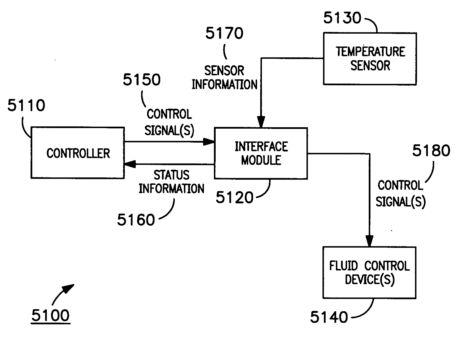
[0060] Reference now should be made to the drawings, in which the same reference numbers are used throughout the different figures to designate the same or similar components. As used herein, the term water-supply system denotes a system that involves components, devices, and / or systems that facilitate the flow of water, such as plumbing components, devices, and / or systems. Although some of the below examples relate to systems involving water, it is to be appreciated that embodiments of the invention are not limited in their application to systems involving water, and can be implemented in settings that involve one or more kinds of fluids. Moreover, various embodiments below can be integrated into larger systems that perform useful operations in addition to monitoring and controlling systems involving water and / or other fluids.

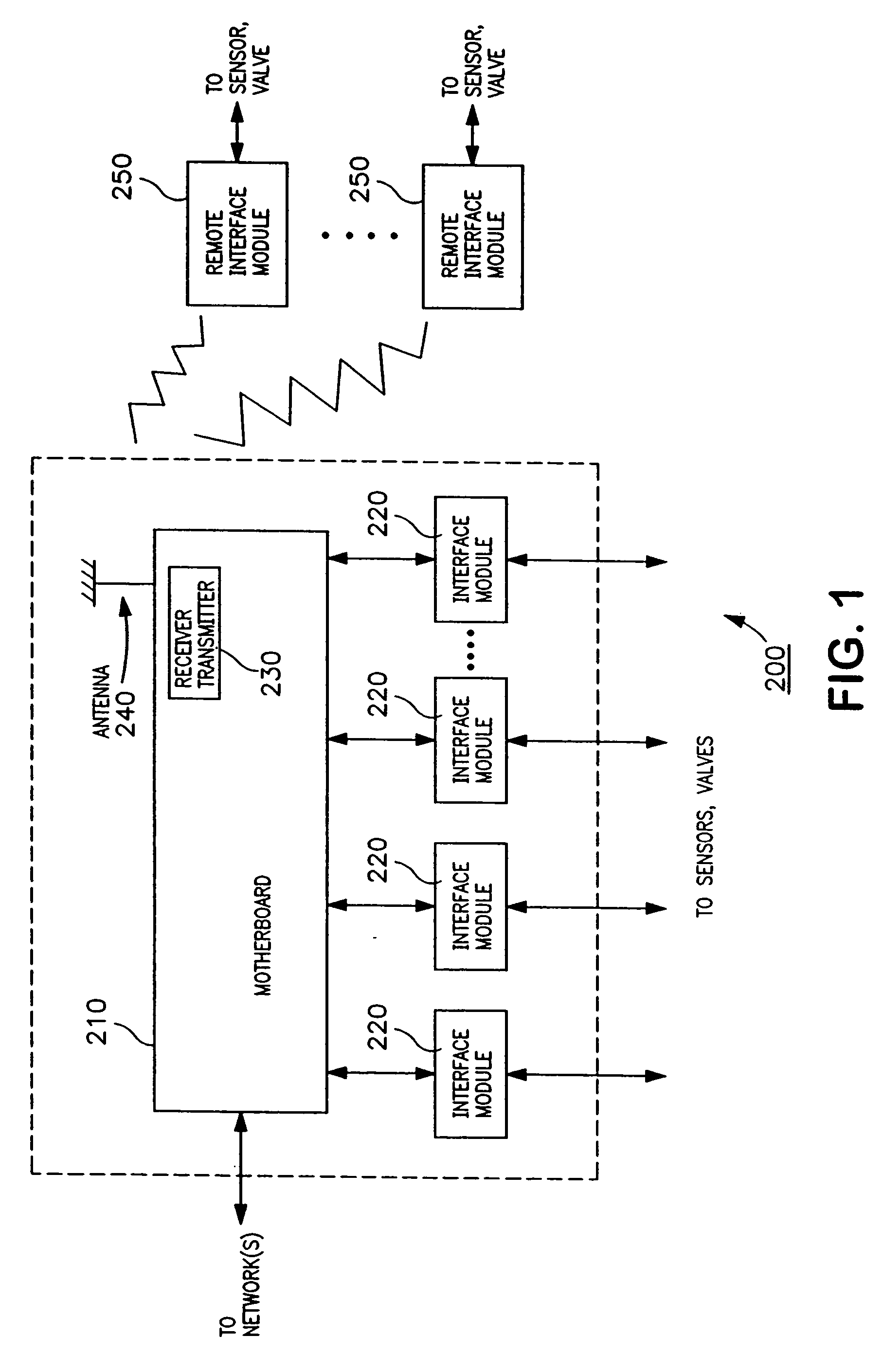
[0061] As described below, in some embodiments, various modules communicate wirelessly. For instance, modules may communicate via USB Wireless, ZigBee, Wi-Fi...


PUM

PropertyMeasurementUnit
Angleaaaaaaaaaa
Temperatureaaaaaaaaaa
Flow rateaaaaaaaaaa

Abstract

Systems and methods for monitoring and controlling water consumption in a water-supply system are disclosed using one or more sensors for generating signals indicative of the operation thereof. In one embodiment, a method of preventing freezing of a water conduit in a water-supply system comprises sensing, with a temperature sensor, a temperature at a location; and, if the sensed temperature falls below a predetermined threshold, sending, to at least one fluid control device interfaced with the conduit, at least one control signal to impede a flow of water through the conduit and to drain water from the conduit.

Description

[0001] This application is a continuation-in-part of U.S. Utility application Ser. No. 11 / 013,249, filed Dec. 15, 2004, which is a continuation-in-part of U.S. Utility application Ser. No. 10 / 668,897, filed Sep. 23, 2003, which is a continuation-in-part of U.S. Utility application Ser. No. 10 / 252,350, filed Sep. 23, 2002, now U.S. Pat. No. 6,766,835, issued Jul. 27, 2004, the contents of all of which are incorporated herein by reference.BACKGROUND OF THE INVENTION [0002] 1. Field of the Invention [0003] The present invention relates to fluid consumption systems in the home and commercial environments. More particularly, the invention relates to automated controls and monitoring of fluid-based systems employing methods and systems for detecting, communicating, and preventing operational failures. [0004] 2. Description of the Related Art [0005] There are various water-consuming fixtures, appliances, and systems in both residential and commercial installations. Typical water-supply sys...

Claims


Application Information

Patent Timeline
IPC IPC(8): H04H9/00B65B3/28G08B21/00B65B57/06H04H60/31
CPCC02F2209/008C02F2209/02C02F2209/03E03B1/00E03B7/071F24D19/1051G01M3/002G01M3/186G01M3/2807G01M3/2815G05B15/02G05B2219/2642Y02A20/15Y10T137/1963F24H15/212F24H15/395F24H15/31F24H15/246F24H15/457F24H15/421F24H15/20F24H15/12F24H15/136F24H15/175F24H15/242
Inventor FIMA, R. GIOVANNI
Owner FIMA R GIOVANNI
Why Eureka
Try Eureka