
Beverage supply device

a technology of a supply device and a supply device, which is applied in the direction of liquid transfer devices, lighting and heating devices, domestic cooling devices, etc., to achieve the effect of effective inhibition of overload operation of compressors, rotational frequency, and promotion of air-cooling of radiators

Inactive Publication Date: 2006-08-03
PANASONIC INTELLECTUAL PROPERTY MANAGEMENT CO LTD
View PDF10 Cites 24 Cited by
  • Summary
  • Abstract
  • Description
  • Claims
  • Application Information

AI Technical Summary

Benefits of technology

The present invention provides a beverage supply device with a cooling system using carbon dioxide as a refrigerant, which is environmentally friendly and efficient. The device includes a cooling unit with a compressor, radiator, pressure reducing means, and evaporator connected by a refrigerant circuit. The device also includes load detecting means for detecting the load on the compressor and control means for controlling the rotational frequency of the compressor based on the output of the load detecting means. The device can improve cooling efficiency and prevent overload operation of the compressor. Additionally, the device includes a blower which air-cools the radiator and the control means controls the fed air amount of the blower based on the output of the load detecting means.

Problems solved by technology

However, such refrigerant is regarded as a cause for destroying an ozone layer, and there has been a demand for development of a refrigerant circuit using a refrigerant which has little influence on global environment from a viewpoint of protecting the global environment.

Method used


Image

  • Beverage supply device
  • Beverage supply device
  • Beverage supply device

Examples


embodiment 1

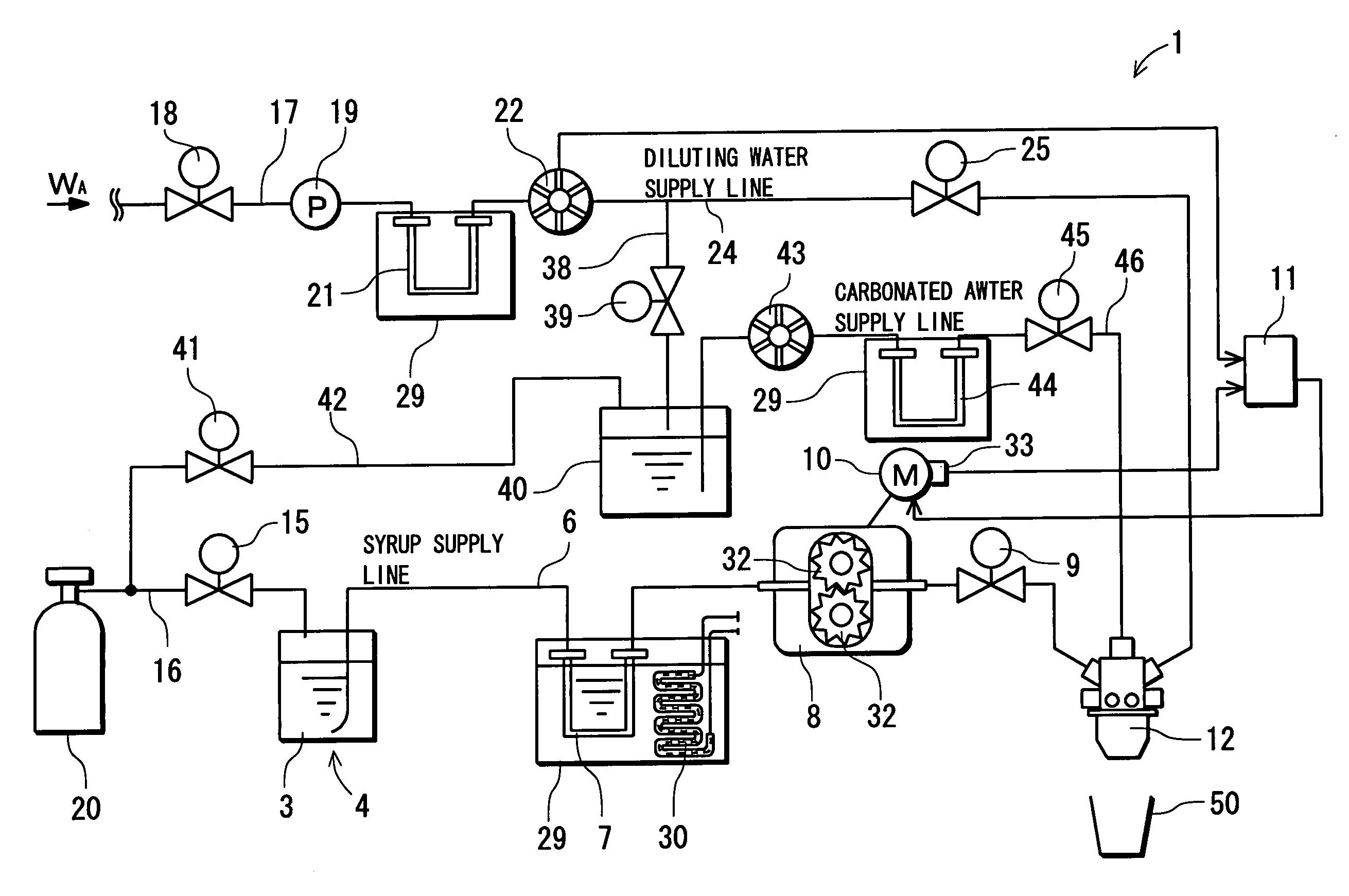
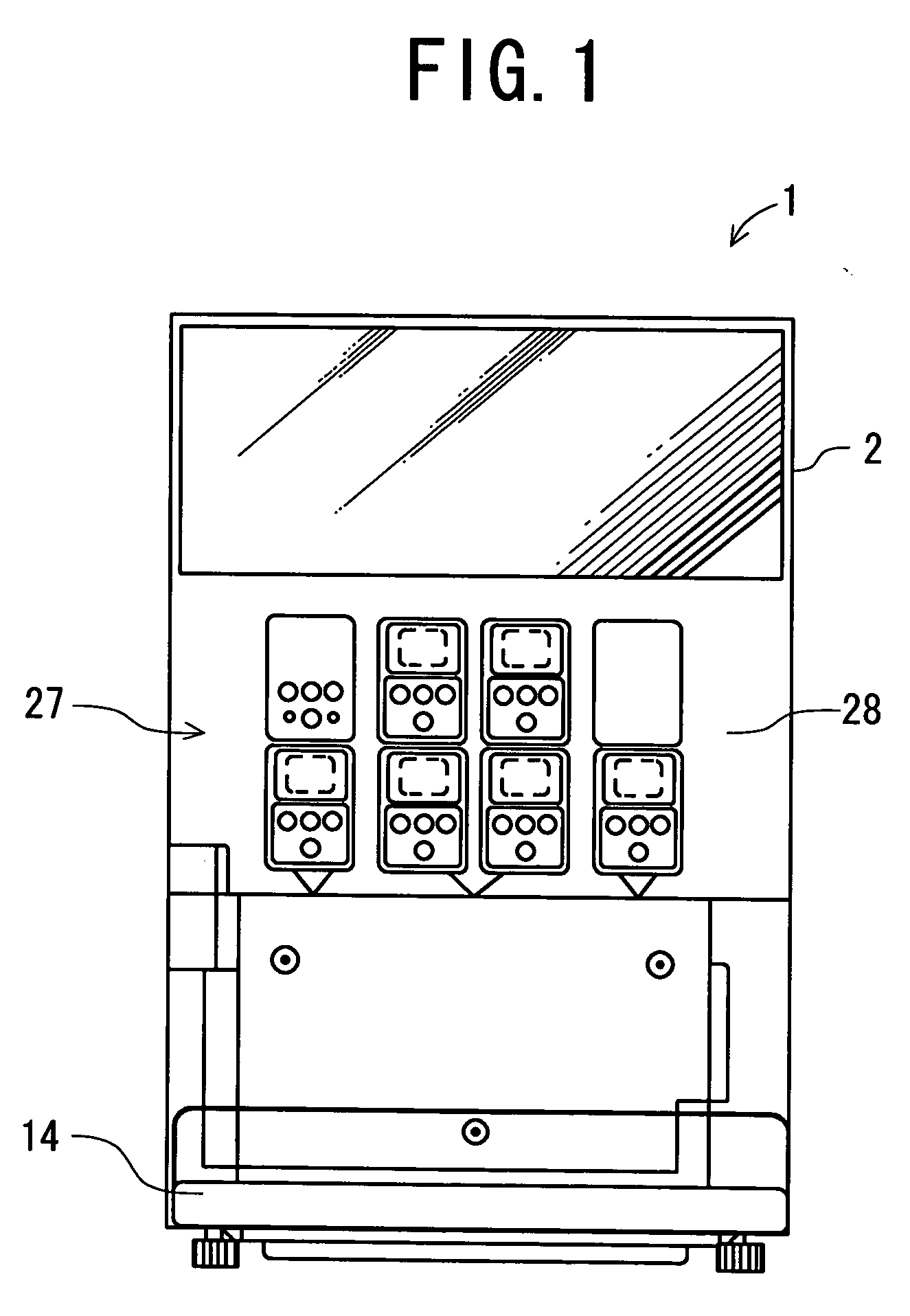
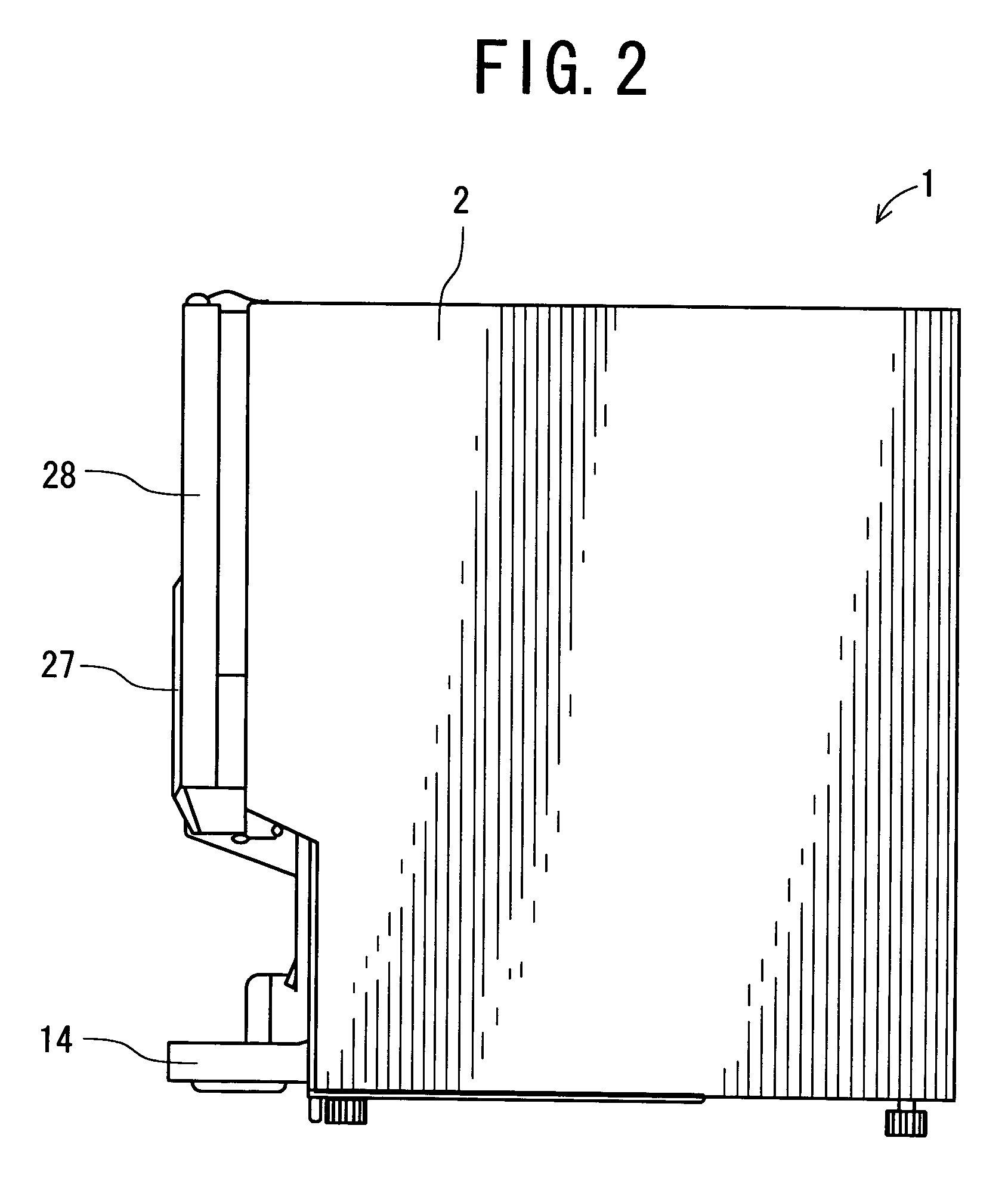
[0030] In a first embodiment, a beverage dispenser 1 is a beverage dispenser for use in a restaurant, a coffee shop or the like, and is a device provided with: a BIB unit (not shown) which supplies neutral beverages such as oolong tea and orange juice; and a tank unit 4 which similarly supplies strongly and lightly carbonated and uncarbonated target beverages. Such beverage dispenser 1 has a structure in which the BIB unit is disposed in a main body 2, and the tank unit 4 is externally connected to the main body. Moreover, the BIB unit is shielded behind an openably closed door 28 positioned in a front face of the main body. It is to be noted that the tank unit 4 will be described later in detail.

[0031] The front face of the opening / closing door 28 is provided with an operation section 27 which supplies the beverage from the tank unit 4 and the BIB unit. The section is provided with operation buttons such as buttons S, M, L, and C / P which select a beverage supply amount or a bevera...

embodiment 2

[0068] There will be described hereinafter use of an outside air temperature sensor in load detecting means in a second embodiment. It is to be noted that a control unit 11 is connected to an outside air temperature sensor 70 as the load detecting means disposed in a main body 2 in order to detect an outside air temperature at which a beverage dispenser 1 is disposed as shown in FIG. 5.

[0069] When the temperature detected by the outside air temperature sensor 70 is higher than, for example, +10°C. and lower than +30° C. in such embodiment, the control unit 11 sets a rotational frequency of a compressor 51 to 50 Hz as described above, and sets the rotational frequency of a blower 53 of a radiator 52 to a usual rotational frequency to operate the blower. Moreover, when the temperature detected by the outside air temperature sensor 70 rises at, for example, +30° C. or more, the control unit 11 lowers the rotational frequency of the compressor 51 at 40 Hz, and operates the blower 53 at...

embodiment 3

[0073] There will be described hereinafter use of a cooling water temperature sensor in load detecting means in a third embodiment. In this case, a cooling water temperature sensor 69 is disposed in a water tank 29 in order to detect a temperature of pooled cooling water. It is assumed that the cooling water temperature sensor 69 is connected to a control unit 11.

[0074] When the temperature detected by the cooling water temperature sensor 69 is higher than, for example, +1° C. and lower than +5° C. in such embodiment, the control unit 11 sets a rotational frequency of a compressor 51 to 50 Hz as described above, and sets the rotational frequency of a blower 53 of a radiator 52 to a usual rotational frequency to operate the blower. Moreover, when the temperature detected by the cooling water temperature sensor 69 rises at, for example, +5° C. or more, the control unit 11 lowers the rotational frequency of the compressor 51 at 40 Hz, and operates the blower 53 at a predetermined high...


PUM


Abstract

An object is to provide a beverage supply device which can cool cooling water in a water tank provided with a beverage cooling pipe by use of a cooling unit using a refrigerant having little influence on global environment, a beverage dispenser is provided with the beverage cooling pipe (syrup cooling pipe, diluting water cooling pipe, carbonated water cooling pipe) disposed in the water tank to store cooling water, the water tank being cooled by an evaporation pipe, the beverage dispenser passes syrup, diluting water, and carbonated water as beverage ingredients through the beverage cooling pipe to extract beverage, and the beverage dispenser comprises: a cooling unit in which a compressor, a radiator, a capillary tube, the evaporation pipe and the like are connected to one another via a pipe to constitute a refrigerant circuit and which is filled with carbon dioxide as the refrigerant.

Description

BACKGROUND OF THE INVENTION [0001] The present invention relates to a beverage supply device where a beverage cooling pipe is disposed in a water tank which stores cooling water and is cooled by a cooling unit, and a beverage or a beverage ingredient is passed through the beverage cooling pipe and extracted. [0002] Heretofore, as described in Japanese Patent Application Laid-Open No. 6-336291, a beverage supply device for cooling and supplying a beverage ingredient such as syrup or a beverage such as cooling water or beer has a constitution in which cooling water is stored in a water tank. The water tank is cooled by an evaporation pipe of a cooling unit to generate ice around the tank. A beverage cooling pipe is disposed in a coiled form in such water tank, and the beverage ingredient or the like is extracted through this beverage cooling pipe to thereby momentarily cool and supply the beverage ingredient. [0003] In the conventional beverage supply device, a refrigerant for use in ...

Claims


Application Information

Patent Timeline
Patent Type & Authority Applications(United States)
IPC IPC(8): B67D5/62B67D7/80
CPCB67D1/0031B67D1/0044B67D1/1231F25B1/10F25B9/008F25B40/00F25B49/025F25B49/027F25B2309/061F25B2600/0253F25B2700/151F25B2700/195F25B2700/2102F25D31/003F25D2700/14
Inventor SAITOH, KAZUHIDEOTSUKA, YUYAIGARASHI, TAKEOSHIRAISHI, NAOYUKIGOITSUKA, AKIRAKAMIYAMA, MASAHIRO
Owner PANASONIC INTELLECTUAL PROPERTY MANAGEMENT CO LTD
Learn More