Identifying unit for working machine and pressure apparatus

a technology of pressure apparatus and working machine, which is applied in the direction of mechanical measuring arrangement, manufacturing tools, instruments, etc., can solve the problem that the control parameters cannot be correctly set for the working head on the movable member, and achieve the effect of reducing troublesome operations, high accuracy and high accuracy

Inactive Publication Date: 2006-08-03
FUJITSU LTD
View PDF17 Cites 58 Cited by
  • Summary
  • Abstract
  • Description
  • Claims
  • Application Information

AI Technical Summary

Benefits of technology

[0014] When the working head is replaced with another one, for example, the load changes in the force sensor in the working machine in the same manner as described above. In general, the individual working head has the specific weight. The working heads can thus be differentiated from each other based on the weight. Accordingly, the controller circuit is allowed to reliably identify the working head after the replacement with a higher accuracy based on the detected load. In addition, the force sensor is utilized to identify the working head. The force sensor is often originally employed to effect processing such as a pressing operation in the working machine. It is not necessary to add a component such as a sensor peculiar to the identification of the contact member into the working machine. The invention can be applied to a conventional working machine without any difficulty.
[0015] The controller circuit may set a control parameter of the working head based on the identification of the working head. Automatic setting of the control parameter in response to the identification of the working head enables reduction in troublesome operations in replacement of the working heads. Since the working head can be identified with a higher accuracy as described above, an erroneous setting of the control parameter can reliably be avoided in the working machine.

Problems solved by technology

When the bar code is erroneously detected in the chip mounter, the control parameters cannot correctly be set for the working head on the movable member in the chip mounter.

Method used


Image

  • Identifying unit for working machine and pressure apparatus
  • Identifying unit for working machine and pressure apparatus
  • Identifying unit for working machine and pressure apparatus

Examples


Embodiment Construction

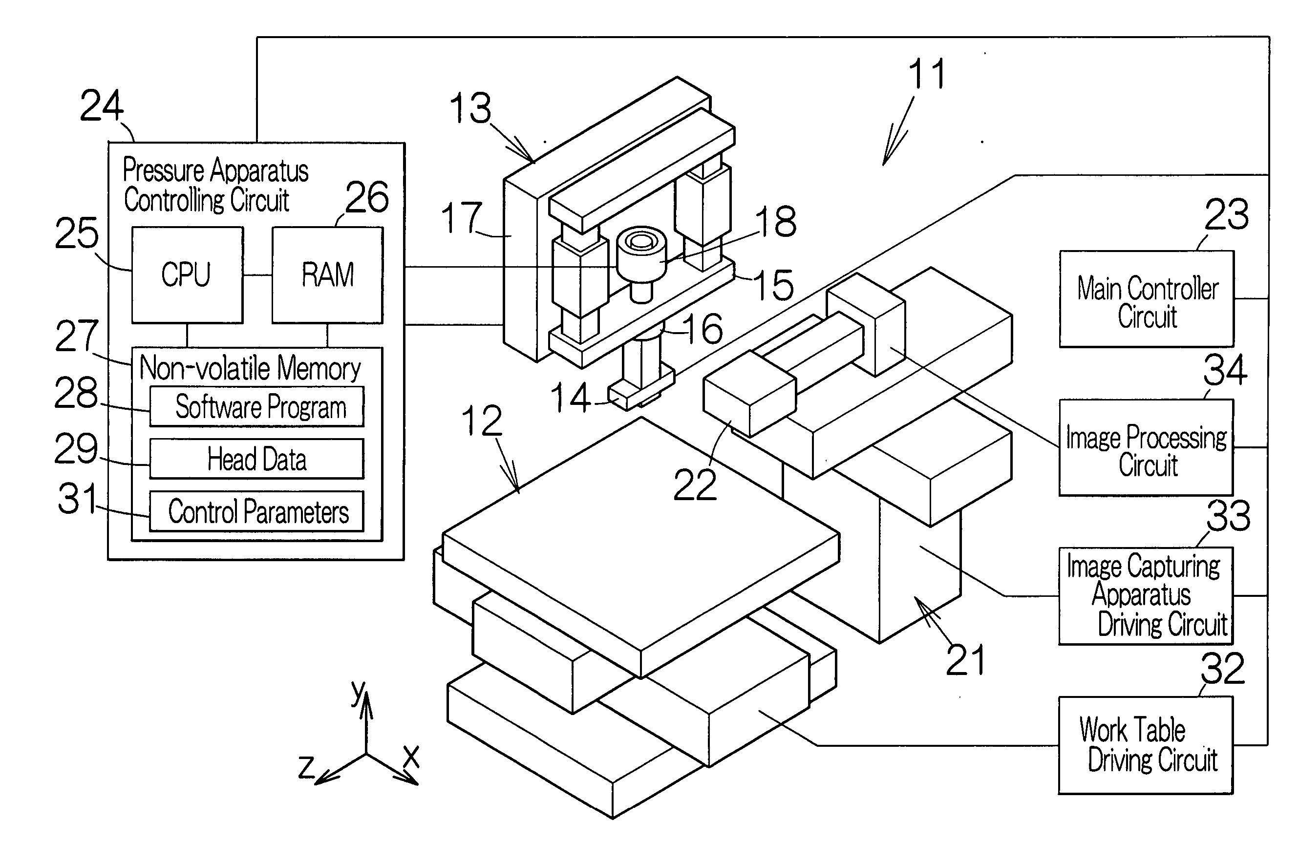
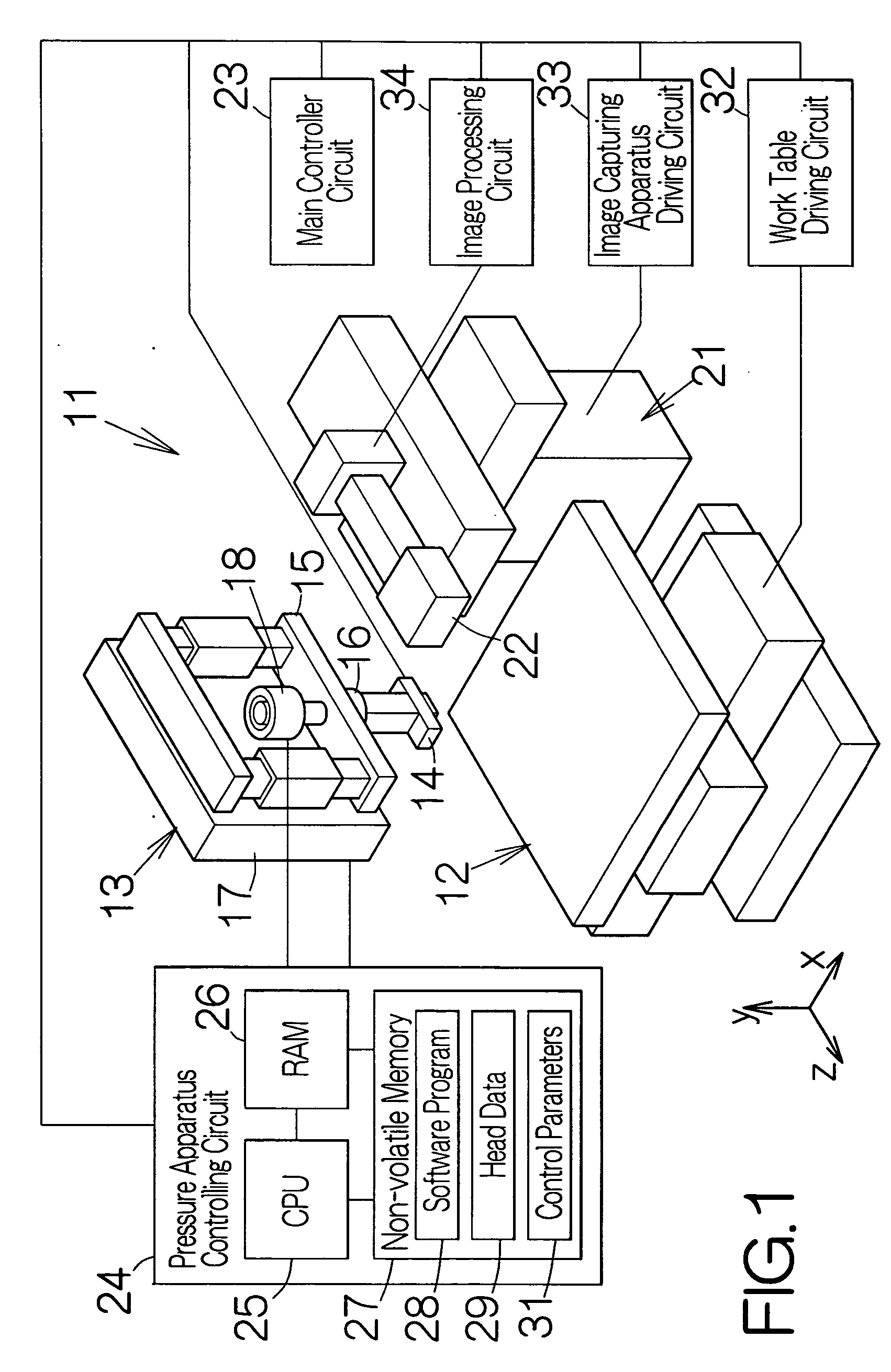
[0021]FIG. 1 schematically illustrates the structure of a chip mounter 11 as a specific example of a working machine according to the present invention. The chip mounter 11 includes a work table 12 defining a top surface along a horizontal plane. The work table 12 is allowed to move in a horizontal direction. A printed circuit board or printed wiring board may be mounted on the top surface of the work table 12.

[0022] Here, a three dimensional coordinate system or xyz-coordinate system is set in the chip mounter 11. The xyz-coordinate system includes the y-axis perpendicular to the top surface of the work table 12, namely the horizontal plane. The work table 12 can be moved in the x-axis and the y-axis. The position of the work table 12 can be determined based on the x-axis and y-axis of the xyz-coordinate system.

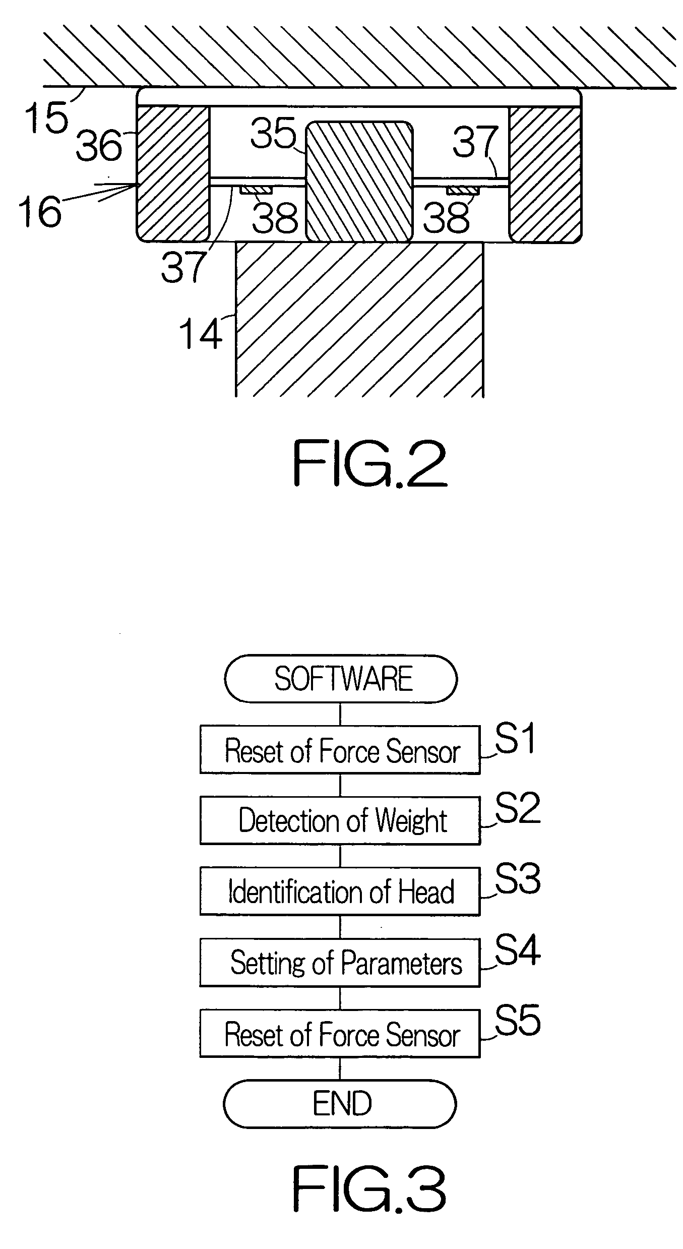
[0023] A pressure apparatus 13 is related to the work table 12. The pressure apparatus 13 includes an ultrasonic head 14 as an example of a contact member or a working hea...


PUM


Abstract

A working machines includes an identifying unit. A force sensor detachably supports a working head in the identifying unit. A controller circuit is designed to identify the working head based on the load detected at the force sensor. When the working head is replaced with another one, the load changes in the force sensor in the identifying unit. In general, the individual working head has the specific weight. The working heads can thus be differentiated from each other based on the weight. Accordingly, the controller circuit is allowed to reliably identify the working head after the replacement with a higher accuracy based on the detected load.

Description

BACKGROUND OF THE INVENTION [0001] 1. Field of the Invention [0002] The present invention relates to a working machine such as a chip mounter designed to mount an electronic circuit chip onto a printed wiring board. In particular, the invention relates to an identifying unit and a pressure apparatus utilized in the working machine. [0003] 2. Description of the Prior Art [0004] A chip mounter is well known as disclosed in Japanese Patent Application Publication No. 2004-55705, for example. The chip mounter includes a working head opposed to the surface of a work stage. A movable member is designed to move toward and away from the surface of the work stage in the chip mounter. The movable member is supported on a guide for relative movement. A load cell is fixed to the movable member. The working head is detachably coupled to the load cell. When the working head is urged against a printed circuit board on the work stage, the applied load is measured at the load cell. [0005] Various wo...

Claims


Application Information

Patent Timeline
Patent Type & Authority Applications(United States)
IPC IPC(8): G01B5/30
CPCY10T483/13H05K13/0413H05K13/0812
Inventor KOBAYASHI, TAIZANTAKADA, EIJI
Owner FUJITSU LTD
Why Eureka
Try Eureka