Actuator for valve lift controller

a technology of actuator and valve, which is applied in the direction of valve arrangement, machine/engine, pressure lubrication, etc., can solve the problems of reducing limiting the position where the actuator can be located, and difficulty in designing the actuator to be small, so as to improve the endurance of both the feed screw mechanism and the motor unit, reduce the size of the actuator, and improve the endurance of the feed screw mechanism. , the effect of simple rotation spindle structur

Inactive Publication Date: 2006-08-03
TOYOTA JIDOSHA KK +1
View PDF4 Cites 7 Cited by
  • Summary
  • Abstract
  • Description
  • Claims
  • Application Information

AI Technical Summary

Benefits of technology

[0012] It is therefore possible to prevent the coils of the motor unit in the second space from suffering from the lubricating oil while lubricating a friction making portion with the lubricating oil in the interior space. It is thus possible to improve endurance of both the feed screw mechanism and the motor unit.
[0013] In addition, the feed screw mechanism, which has a relatively simple structure of the rotation spindle and the screwed shaft, is used as a mechanism to convert the rotational movement of the motor unit to the linear movement of the control shaft. It is therefore possible to reduce the size of the actuator.

Problems solved by technology

It is therefore difficult to design the actuator to be small.
Thus, positions where the actuator can be located may be limited.
The inventers, however, found a problem in decreasing the size of the actuator in the case that the feed screw mechanism and the motor unit are installed in the same housing.
Especially, if the motor unit is designed to drive a spindle by exiting a coil, the lubricating oil causes defect in the motor unit such as disconnection.

Method used


Image

  • Actuator for valve lift controller
  • Actuator for valve lift controller
  • Actuator for valve lift controller

Examples


Embodiment Construction

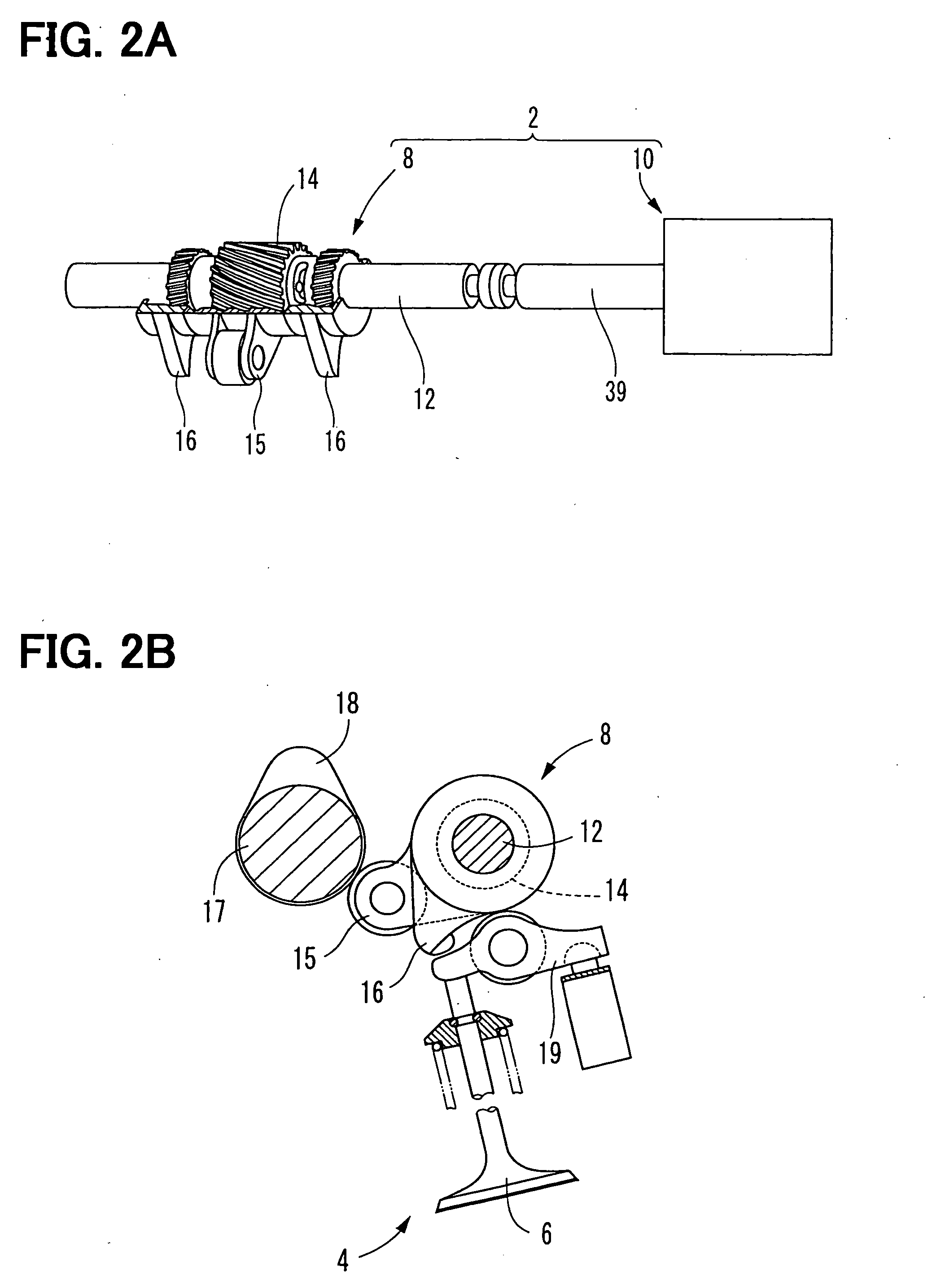
[0019] As shown in FIGS. 2A and 2B, a valve lift controller 2 according to an embodiment includes a changing mechanism 8 and an actuator 10, and controls a lift amount of an intake valve 6 of an engine 4.

[0020] The changing mechanism 8, which is disclosed in for example JP 2001-263015A, is mounted on the engine 4 and includes a control shaft 12, a slide gear 14, an input unit 15, and swinging cams 16. The slide gear 14 is linearly movable along with the control shaft 12 in the axial direction of the control shaft 12 and is engaged with a helical spline on inner surfaces of the input unit 15 and the swinging cams 16. A difference between rotational phases of the input unit 15 and the swinging cams 16 around the axial direction changes according to a position of the control shaft 12 in the axial direction.

[0021] The input unit 15 is in contact with an intake cam 18 of a camshaft 17, and one of the swinging cams 16 can be in contact with a rocker arm 19 of the intake valve 6. A swing...


PUM


Abstract

An actuator for a valve lift controller comprises a case forming a first and second spaces therein. The first space is supplied with lubricating fluid. The actuator further comprises a feed screw mechanism including a cylindrical spindle and a screw, and converts a rotational movement of the spindle to a linear movement of the screw. The spindle includes a first end portion open to the first space and a second end portion closed to the second space therein. The screw straddles borders between an interior of the spindle, the first space, and an external space. The actuator includes a motor unit which is located in the second space and rotates the spindle. The actuator further includes a sealing member sealing a gap between the case and the spindle to separate the first and second spaces.

Description

CROSS REFERENCE TO RELATED APPLICATION [0001] This application is based on Japanese patent application No. 2005-25306 filed on Feb. 1, 2005, the disclosure of which is incorporated herein by reference. FIELD OF THE INVENTION [0002] The present invention relates to a valve lift controller for controlling a lift amount of an intake valve and / or an exhaust valve of an internal combustion engine (hereafter referred to simply as an engine). BACKGROUND OF THE INVENTION [0003] In a conventional valve lift controller, several types of actuators are used for linearly driving an axis of a changing mechanism which controls a lift amount of a valve based on a position of the axis. For example, an actuator is described in US 2004-0083997A1 (JP 2004-150332A) which converts, by means of a reduction mechanism and a cam mechanism, a rotational driving force into a linear driving force and apply the linear driving force to the axis of the changing mechanism. [0004] The conventional actuator, however,...

Claims


Application Information

Patent Timeline
Patent Type & Authority Applications(United States)
IPC IPC(8): F01L1/34
CPCF01L1/185F01L1/2405F01L13/0015F01L13/0063F01L2105/00F01L2820/032F01L2305/00
Inventor KIMURA, KIYOSHIYOSHIYAMA, SHIGERUITOH, TAKUINABA, HIDEOYAMAGUCHI, JOJIKAMESHIMA, AKIHIKOFUJIYOSHI, TOSHIKI
Owner TOYOTA JIDOSHA KK
Why Eureka
Try Eureka