
Rotation angle detector

Inactive Publication Date: 2006-08-03
DENSO CORP +1
View PDF5 Cites 11 Cited by
  • Summary
  • Abstract
  • Description
  • Claims
  • Application Information

AI Technical Summary

Benefits of technology

[0011] A rotation angle detector for detecting change in the magnetic flux by the magnetic sensor has the magnetic sensor being disposed at a position in a space between an outer surface of a shaft and a periphery of the magnetic flux generation unit between both ends of the shaft. A supplementary magnet is disposed in a space that is within a circular trace of the magnetic sensor around the shaft for evenly distributing the magnetic flux generated by the magnetic flux generation unit. In this manner, the magnetic sensor can detect the change in the magnetic flux without an influence of the shaft made with the magnetic material, thereby enabling detection of rotation angle of the magnetic flux generation unit relative to the magnetic sensor.
[0020] The magnetic flux generation unit uses a permanent magnet for generating the magnetic flux, and the permanent magnet and the supplementary magnet are integrally formed in one body. In this manner, increase of the cost for an additional part and assembly will be prevented.

Problems solved by technology

Therefore, the rotation angle cannot be correctly detected when the magnetic flux is warped in a space surrounded by the cylindrical magnet 3.
That is, the direction of the magnetic flux is not uniformly aligned to a certain direction, thereby increasing errors in the detection signal caused by a small displacement of the magnetic sensors or the like.
As a result, a nominal assembly displacement of the first or second sensors 6, 7 suffers from an increased amount of warpage in the magnetic flux as the error in the detection signal.

Method used


Image

  • Rotation angle detector
  • Rotation angle detector
  • Rotation angle detector

Examples


first embodiment

[0053] A first embodiment of the rotation angle detector in the present invention is described with reference to FIGS. 1A to 3.

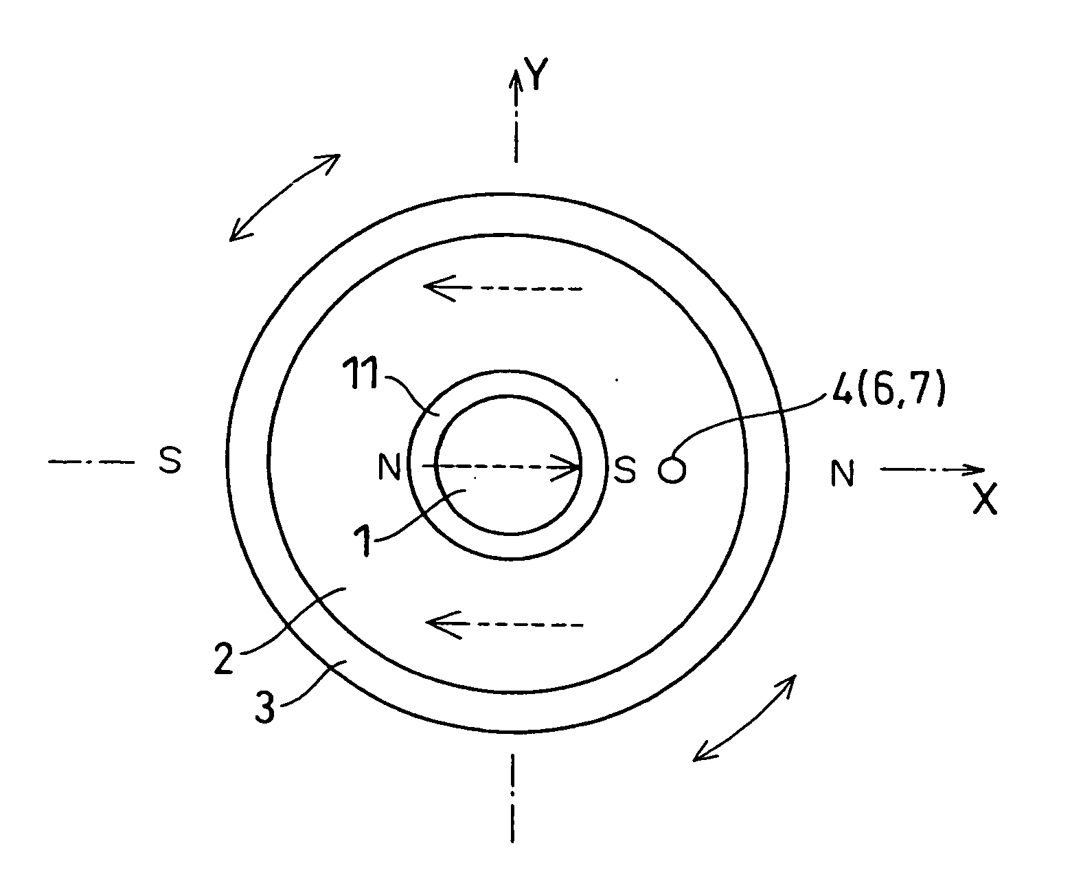
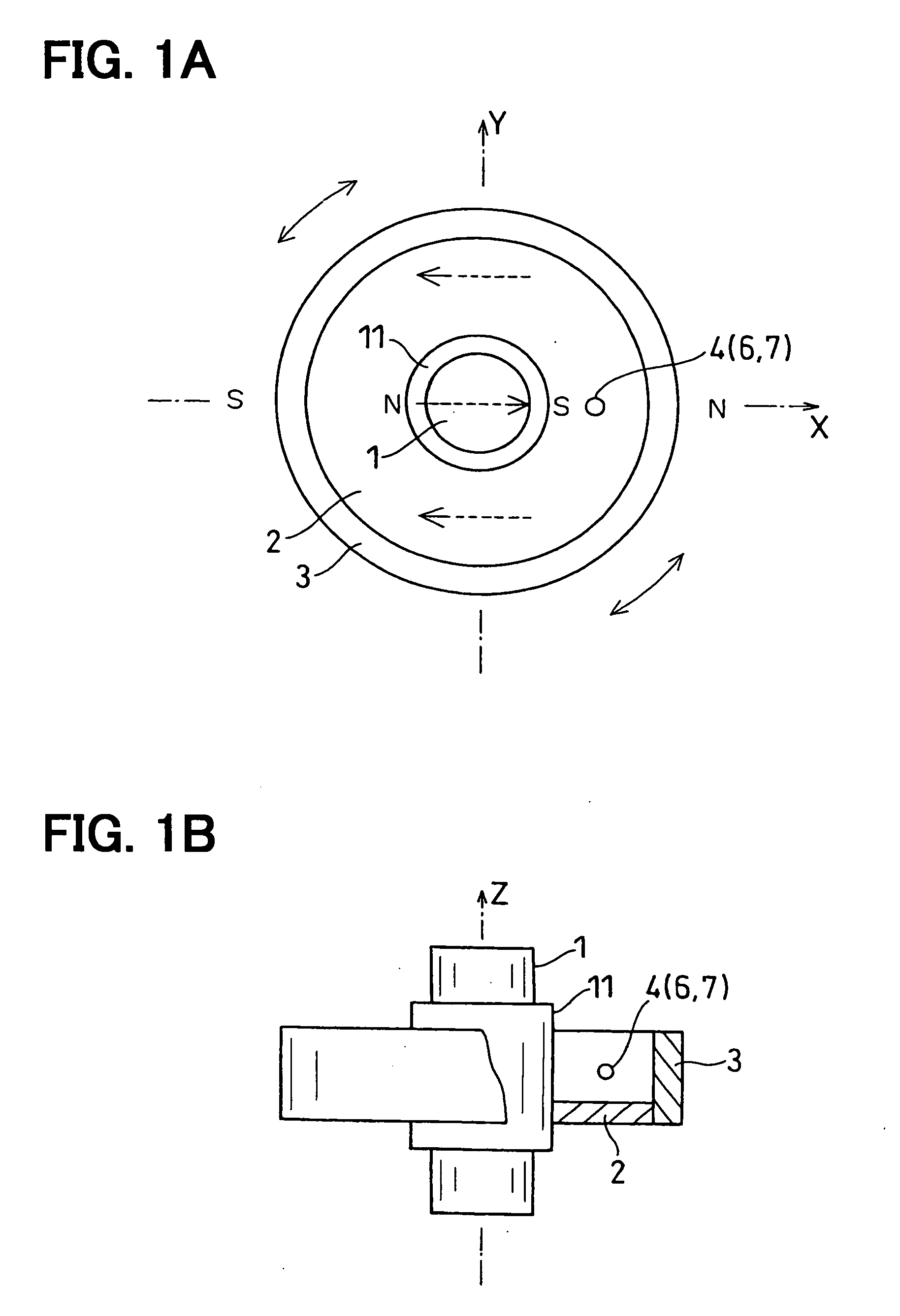
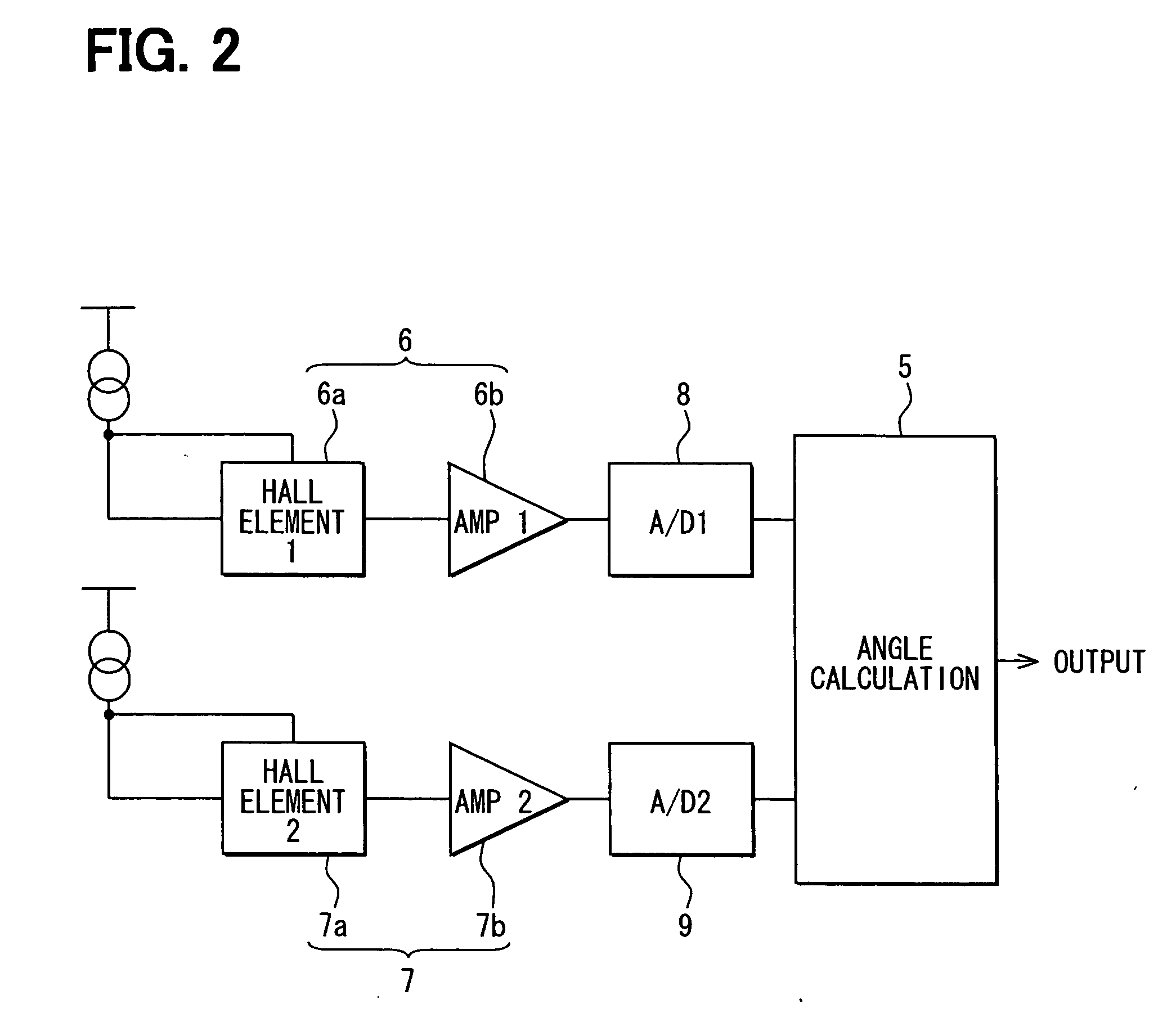
[0054]FIGS. 1A, 1B and 2 show a top view, a side view with a partial cross-section and a schematic diagram of an electric circuit of the rotation angle detector.

[0055] In the following description, X axis and Y axis are arranged orthogonally to each other in a plane that is perpendicular to the shaft, and Z axis is aligned with the shaft.

[0056] The rotation angle detector in the first embodiment includes a shaft 1 (i.e., a rotating member in this embodiment), a cylindrical magnet 3 fixedly disposed on the shaft 1 by using a supporting member 2, and a magnetic detector 4 and an angle calculation unit 5 both disposed on a member (not shown in the drawing) that relatively rotates to the shaft 1 (e.g., a circuit board or the like disposed on, for example, a housing).

[0057] The shaft 1 takes a cylindrical form made with the magnetic material (e.g., an iron or...

second embodiment

[0074] A second embodiment of the present invention is described with reference to FIGS. 4A and 4B. In the second embodiment, like numbers represent like parts as is represented in the first embodiment.

[0075] The second embodiment uses the magnet 3 in a disk form instead of the cylindrical form used in the first embodiment. The permanent magnet 3 is in the form of disk with a constant thickness. The center of the magnet 3 coincides with the center (i.e., the Z axis) of the shaft 1, and an inner circumference of the magnet 3 is directly attached on the shaft 1. Therefore, the magnet 3 integrally rotate with the shaft 1.

[0076] The magnetic poles in the magnet 3 are aligned with a line that is perpendicular to the Z axis. In the second embodiment, the magnetic flux is aligned with an arrow in a broken line in FIG. 4A with an assistance of the supplementary magnet 11 directly attached to the shaft 1 in an inner space that extends from the magnetic sensor 4 toward the shaft 1. The magn...

third embodiment

[0081] A third embodiment of the present invention is described with reference to FIGS. 5A and 5B. In the third embodiment, like numbers represent like parts as is represented in the first embodiment.

[0082] The third embodiment uses two of the magnets 3 in a disk form instead of the cylindrical form used in the first embodiment. Two of the permanent magnet 3 has the same constant thickness and the same magnetic intensity with the same dimensions. The center of the magnets 3 coincide with the center (i.e., the Z axis) of the shaft 1, and an inner circumference of the magnets 3 are directly attached on the shaft 1 having a predetermined amount of space interposed therebetween. The magnets 3 integrally rotate with the shaft 1 made with the magnetic material.

[0083] The supplementary magnet 11 is in a form of a cylinder disposed in the space inside of the magnetic sensor 4 having a constant radial thickness. The shaft 1 and the magnet 11 integrally rotate with their center points being...


PUM


Abstract

A rotation angle detector for detecting change in the magnetic flux has a magnetic sensor being disposed at a position in a space between an outer surface of a shaft and a periphery of the magnetic flux generation means. A supplementary magnet is also used in a space that is enclosed in a circular trace of the magnetic sensor around the shaft for even distribution of the magnetic flux generated by the magnetic flux generation means.

Description

CROSS REFERENCE TO RELATED APPLICATION [0001] This application is based on and claims the benefit of priority of Japanese Patent Application No. 2005-27686 filed on Feb. 3, 2005, and Japanese Patent Application No. 2005-361914 filed on Dec. 15, 2005, the disclosure of which are incorporated herein by reference. FIELD OF THE INVENTION [0002] The present invention generally relates to a rotation angle detector.BACKGROUND OF THE INVENTION [0003] Conventionally, a rotation angle detector detects a rotation angle by using a magnetic detector at a periphery of a rotating magnet (e.g., a permanent magnet, a permanent magnet with a yoke or the like) that generates magnetic flux. [0004]FIGS. 13A and 13B shows a rotation angle detector that includes a shaft 1, a cylindrical magnet 3 attached to the shaft 1, and a magnetic detector 4 disposed at a rotation center of the magnet 3 for detecting magnetic flux generated by the magnet 3. The magnet 3 is an example of a magnetic flux generation mean...

Claims


Application Information

Patent Timeline
IPC IPC(8): G01B7/30
CPCG01D5/24438G01D5/145
Inventor SHIMOMURA, OSAMUNAKAMURA, TSUTOMUTAKEDA, KENJIKAWASHIMA, TAKASHIKITANAKA, TATSUYAMATSUMOTO, KOICHIROBAN, TAKAO
Owner DENSO CORP
Features
  • Generate Ideas
  • Intellectual Property
  • Life Sciences
  • Materials
  • Tech Scout
  • Unparalleled Data Quality
  • Higher Quality Content
  • 60% Fewer Hallucinations
Learn More