Method and a device for voltage measurement in a high-voltage conductor

a high-voltage conductor and voltage measurement technology, applied in the direction of voltage dividers, resistance/reactance/impedence, instruments, etc., can solve the problems of auxiliary voltage dividers that require considerable space, said test taps require costly bushings, and are less suitable for measuring harmonics. , to achieve the effect of simple design, weight and cos

a high-voltage conductor and voltage measurement technology, applied in the direction of voltage dividers, resistance/reactance/impedence, instruments, etc., can solve the problems of auxiliary voltage dividers that require considerable space, said test taps require costly bushings, and are less suitable for measuring harmonics. , to achieve the effect of simple design, weight and cos

US20060170432A1Active Publication Date: 2006-08-03ABB POWER GRIDS SWITZERLAND AG

Image

  • Method and a device for voltage measurement in a high-voltage conductor
  • Method and a device for voltage measurement in a high-voltage conductor
  • Method and a device for voltage measurement in a high-voltage conductor

Examples


Embodiment Construction

[0042] The following description relates to the method as well as the measuring equipment

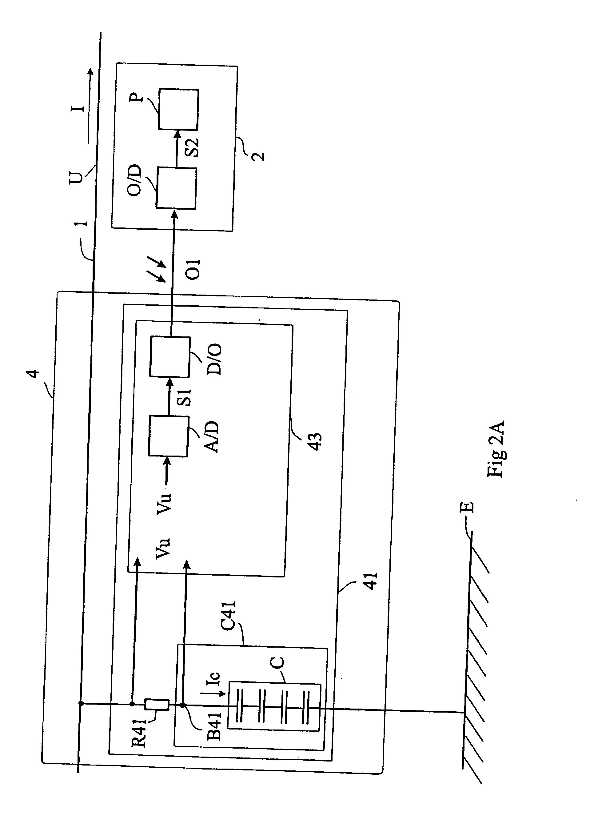
[0043]FIG. 2A shows, in the form of a single-line diagram and a block diagram, measuring equipment 4 for sensing a voltage by a voltage-measuring means 41 for the purpose of forming measured values representing voltage on a high-voltage conductor 1, and control equipment 2. The measuring equipment is comprised in a high-voltage installation. The control equipment is placed in a control room.

[0044] Typical values of the high-voltage conductor 1 are 200-4000 A and 145-550 kV.

[0045] The voltage-measuring means 41 comprises a resistor R41, a digital / optical measurement value transformer 43, and capacitor equipment C41 comprising a coupling capacitor C with an external voltage terminal B41.

[0046] The resistor R41 is connected between the high-voltage conductor 1, at high-voltage level, and the external voltage terminal B41 on the capacitor equipment, the second pole of which is connected to groun...


PUM


Abstract

Measuring equipment for forming a measured value for voltage representing an ac voltage on a high-voltage conductor. The measuring equipment includes capacitor equipment with a known capacitance for connection between the high-voltage conductor and ground potential. The measuring equipment further includes a current-measurer for sensing a capacitor current flowing through the capacitor equipment and for forming the measured value for voltage in dependence on the capacitor current.

Description

TECHNICAL FIELD [0001] The present invention relates to measuring equipment and to a method for sensing a voltage in a high-voltage conductor. [0002] It is to be understood that the term measurement value transformer in the following text means a unit that converts a measurement signal from one transmission medium to another, in this case between an analog electrical signal and an optical signal. BACKGROUND ART [0003] In a high-voltage (HV) installation, or an extra-high-voltage (EHV) installation, there is a need to establish magnitudes of electric variables such as, for example, current, voltage, power and energy, and, as in this case, the occurrence of harmonics of current and voltage. [0004] An extra-high-voltage installation or a high-voltage installation means in this application an installation that may typically comprise electrical equipment such as ac machines, transformers, high-voltage capacitors, loads / burdens, lines, cables, busbars, disconnecting switches and breakers,...

Claims


Application Information

Patent Timeline
03 Aug 2006
Publication
US20060170432A1
IPC
G01R27/26; G01R15/06; G01R15/16
CPC
G01R15/06; G01R15/16
Inventors
ADOLFSSON, MORGAN; LUNDQUIST, JAN