Image conversion apparatus

a conversion apparatus and image technology, applied in the field of image conversion apparatus, can solve the problems of image distortion, difficult control of output at the target code amount, and the value after the decimal point, so as to reduce the deterioration of picture quality

Inactive Publication Date: 2006-08-03
PANASONIC CORP
View PDF3 Cites 30 Cited by
  • Summary
  • Abstract
  • Description
  • Claims
  • Application Information

AI Technical Summary

Benefits of technology

[0022] The present invention was conceived in view of the stated problems, with an object of providing an image conversion apparatus that performs code amount reduct

Problems solved by technology

However, when moving picture encoded data is transmitted to a decoding apparatus connected to a transmission path, such as radio communication, that has a narrow bandwidth, a problem of image distortion occurs when the moving picture is played by the decoding apparatus if the moving picture encoded data is transmitted at the original rate.
However, since the aforementioned re-quantized DCT coefficients c[i] need to be made into integers, a problem arises of how to deal with the

Method used


Image

  • Image conversion apparatus
  • Image conversion apparatus
  • Image conversion apparatus

Examples


first embodiment

1. FIRST EMBODIMENT

[0073] The following describes a rate conversion apparatus 10 as a first embodiment of the present invention with reference to the drawings.

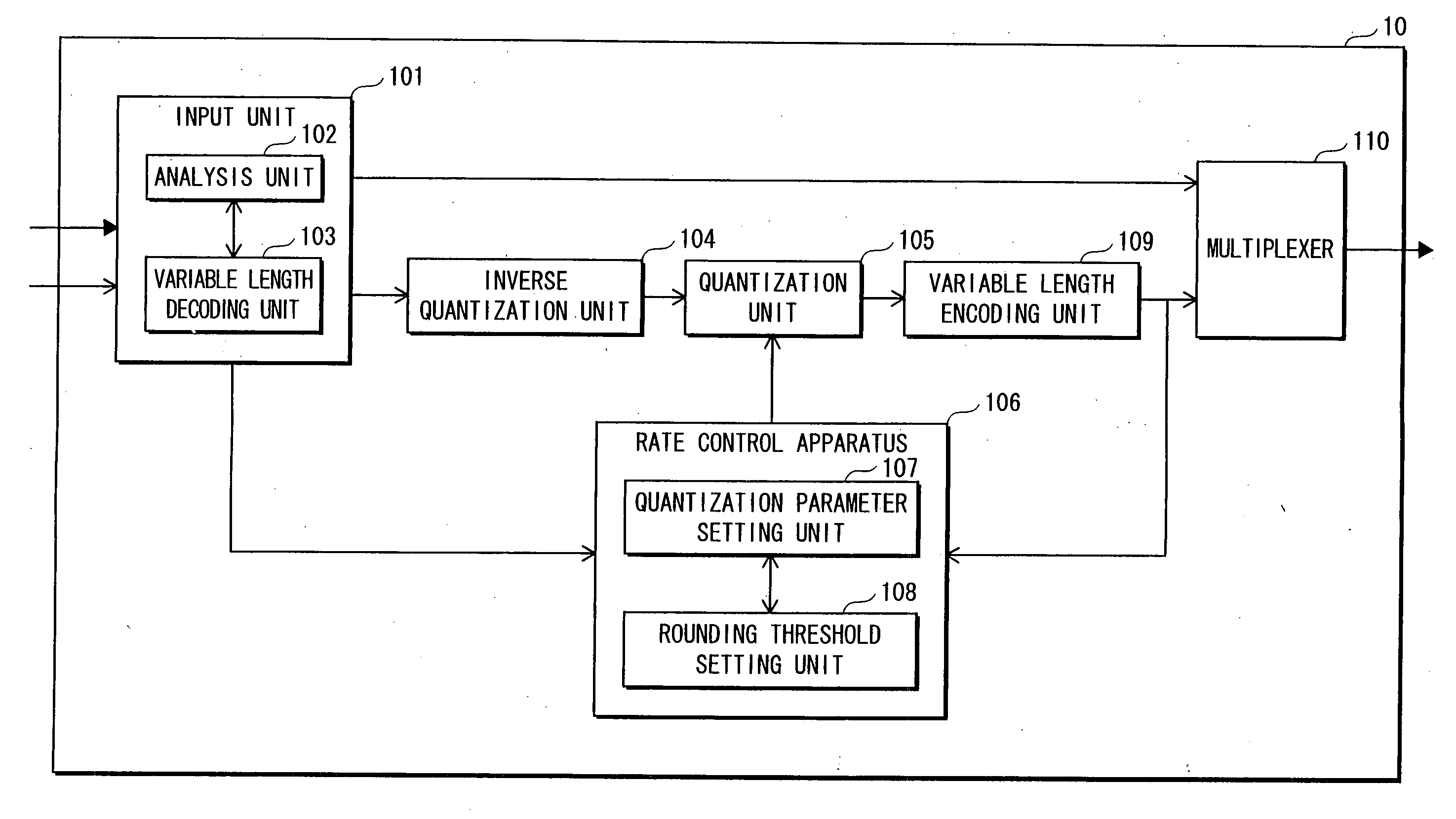
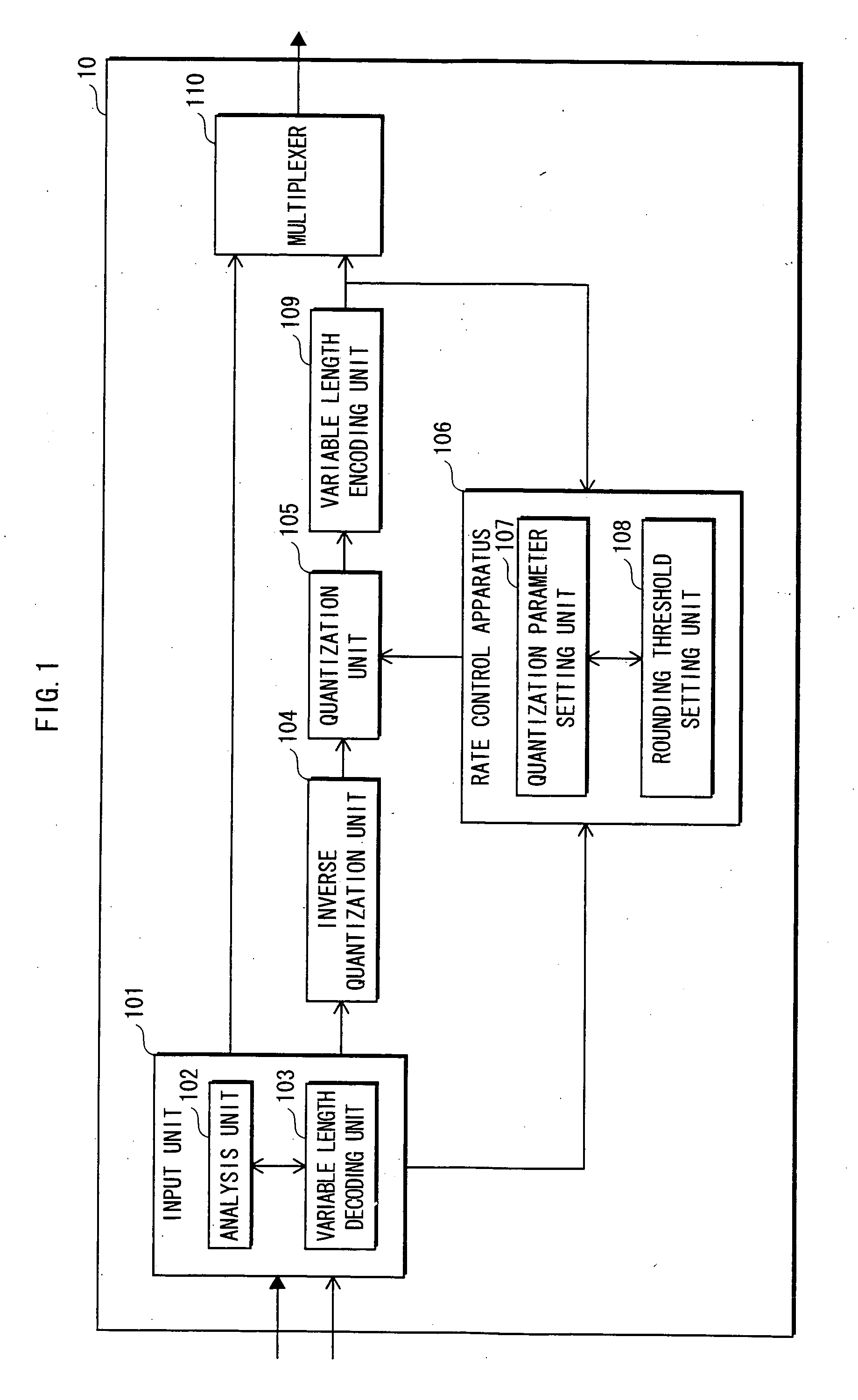
[0074]FIG. 1 is a block diagram showing the structure of the rate conversion apparatus 10. As shown in FIG. 1, the rate conversion apparatus 10 is composed of an input unit 101, an inverse quantization unit 104, a quantization unit 105, a rate control unit 106, a variable length encoding unit 109 and a multiplexer 110. The input unit 101 has an analysis unit 102 and a variable length decoding unit 103, and the rate control unit 106 has a quantization parameter setting unit 107 and a rounding threshold value setting unit 108. The rate conversion apparatus 10 is composed, specifically, of a microprocessor, a ROM, a RAM and the like.

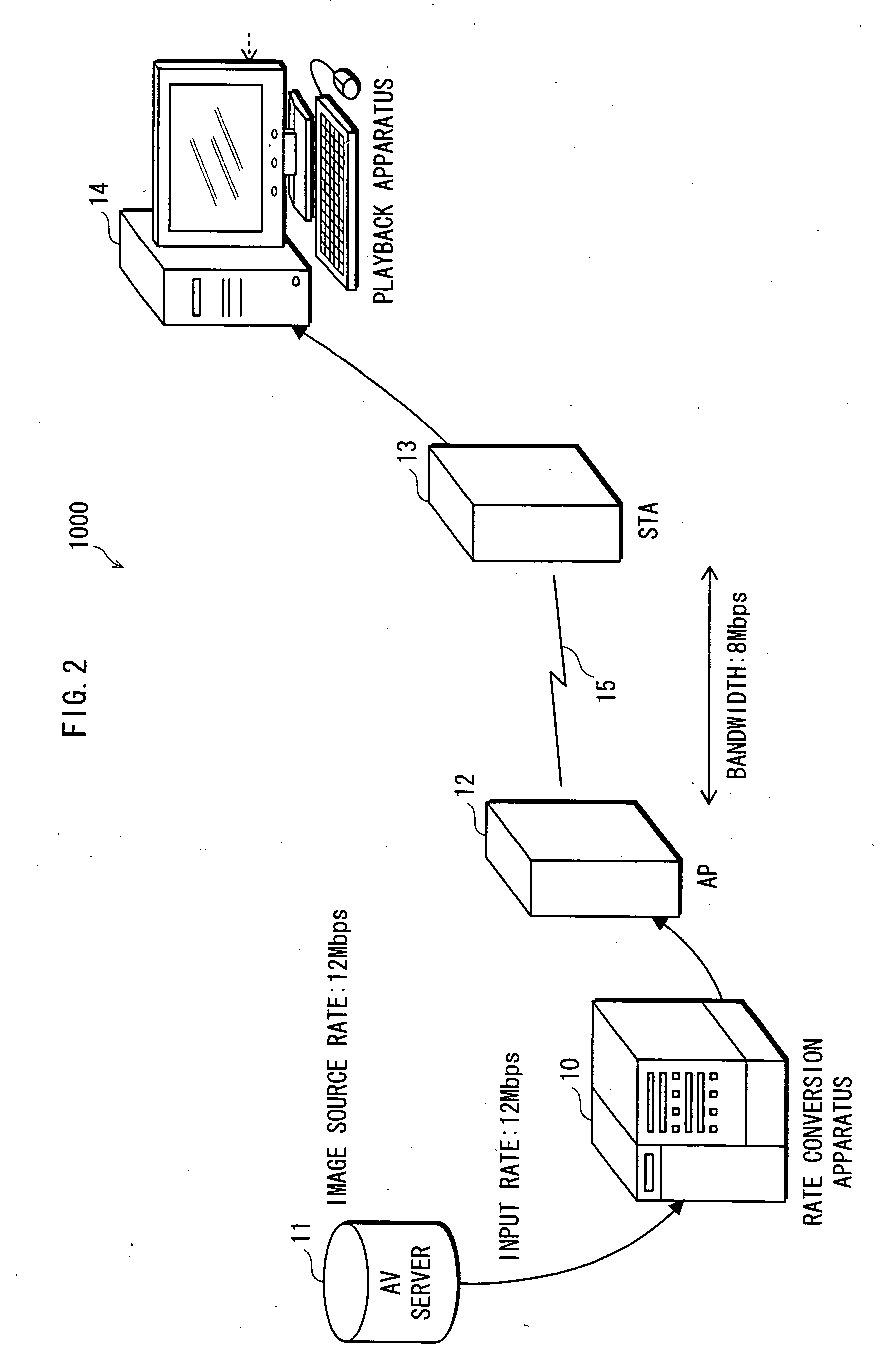
[0075] The rate conversion apparatus 10 has functions of converting the bit rate of an input image, and outputting an output image at an output rate that differs to the input rate.

[0076] The follow...

second embodiment

2. SECOND EMBODIMENT

[0181] The following describes a rate conversion apparatus that is a second embodiment of the present invention.

Structure

[0182] The structure of the rate conversion apparatus of the second embodiment is not illustrated.

[0183] As with the rate conversion apparatus 10 shown in FIG. 1, the rate conversion apparatus of the second embodiment is composed of an input unit, an inverse quantization unit, a quantization unit, a rate control unit, a variable length encoding unit and a multiplexer. The input unit includes an analysis unit and a variable length decoding unit, and the rate control unit includes a quantization parameter setting unit and a rounding threshold value setting unit.

[0184] Whereas “0.5” and “1” were used selectively as the rounding threshold value in re-quantization processing in the first embodiment, in the second embodiment, the rounding threshold value setting unit stores rounding threshold value candidate information 160 composed of “0.5”, “0....

third embodiment

3. THIRD EMBODIMENT

[0200] The following describes a rate conversion apparatus that is a third embodiment of the present invention.

Structure

[0201] The structure of the rate conversion apparatus of the third embodiment is not illustrated.

[0202] As with the rate conversion apparatus 10 shown in FIG. 1, the rate conversion apparatus of the third embodiment is composed of an input unit, an inverse quantization unit, a quantization unit, a rate control unit, a variable length encoding unit and a multiplexer. The input unit includes an analysis unit and a variable length decoding unit, and the rate control unit includes a quantization parameter setting unit and a rounding threshold value setting unit.

[0203] The rate conversion apparatuses of the first and second embodiment use a quantization scale as the quantization parameter. In other words, rate conversion processing is performed by changing the first quantization scale Q_scale1 to the second quantization scale Q_scale2. In contrast...


PUM


Abstract

A rate conversion apparatus 10 includes a quantization parameter setting unit 107 and a rounding threshold value setting unit 108. The quantization parameter setting unit 107 determines a quantization parameter change amount according to a code amount of encoded data output from a variable length encoding unit 109 and a target code amount. The quantization parameter setting unit 107 adds a first quantization amount used in an image before conversion to the quantization parameter change amount, to generate a second quantization parameter to be used in re-quantization processing in a quantization unit 105. The rounding threshold value setting unit 108 sets the rounding threshold value according to the quantization parameter change amount. The quantization unit 105 performs re-quantization using the second quantization parameter and the rounding threshold value.

Description

[0001] This application is based on application No. 2005-000363 filed in Japan, the content of which is hereby incorporated by reference. BACKGROUND OF THE INVENTION [0002] (1) Field of the Invention [0003] The present invention relates to a technique for reducing the amount of code of moving picture encoded data to convert the bit rate thereof, and in particular to a technique for reducing deterioration of picture quality of the moving picture encoded data obtained as a result of the conversion. [0004] (2) Description of the Related Art [0005] Compression encoding techniques are used for efficiently transmitting and recording digital moving pictures, MPEG-2 (Moving Picture Experts Group phase 2) being a commonly-known standard that is a compression encoding method for digital video and audio. In MPEG-2, efficient compression encoding of a moving picture composed of a series of frames is achieved in the following way. First, redundancy in the time axis direction thereof is eliminate...

Claims


Application Information

Patent Timeline
IPC IPC(8): H04N11/04H04B1/66H04N7/12H04N11/02H04N19/60H03M7/30H04N19/126H04N19/132H04N19/134H04N19/136H04N19/146H04N19/159H04N19/177H04N19/186H04N19/196H04N19/503H04N19/61H04N19/625H04N19/91
CPCH04N19/159H04N19/15H04N19/61H04N19/40H04N19/186H04N19/152H04N19/177H04N19/124
Inventor MASUDA, YOICHIHAMAMOTO, YASUOHAYASHINO, HIROSHI
Owner PANASONIC CORP
Why Eureka
Try Eureka