Developing apparatus

a technology of developing apparatus and developing chamber, which is applied in the direction of electrographic process apparatus, instruments, optics, etc., can solve the problems of difficult compatibility with ghost image fault, reduced fog performance, and inability to remove toner, so as to prevent fog, improve the uniformity of thin lines, and prevent uneven density

Active Publication Date: 2006-08-03
CANON KK
View PDF24 Cites 12 Cited by
  • Summary
  • Abstract
  • Description
  • Claims
  • Application Information

AI Technical Summary

Benefits of technology

[0017] It is another object of the present invention to provide a developing apparatus which prevents fog.
[0018] It is another object of the present invention to provide a developing apparatus which prevents the occurrence of a ghost image.
[0019] It is another object of the present invention to provide a developing apparatus which prevents uneven density.
[0020] It is another object of the present invention to provide a developing apparatus which improves the uniformity of a thin line.
[0021] It is another object of the present invention to provide a developing apparatus which prevents the edge of an image from becoming dark or light.

Problems solved by technology

In the nonmagnetic contact developing method of item (1) above, a reduction in fog performance has been a problem.
For the prevention of the reduction in the characteristic of the toner, it is also possible to weaken the frictionally contacting force of the elastic roller, but the compatibility thereof with the fault of a ghost image is difficult.
Also, the presence of a ghost means that there is some toner not stripped off, but residual on the developing roller.
The adjustment of the frictionally contacting force has a problem not only being contrary from the viewpoints of the fog and the ghost, but also contrary in the single matter of fog.
Also, there has arisen the problem that when the characteristic of the toner is reduced, the toner is liable to be affected by the circulation thereof in the developing device.
On the other hand, the toner being circulated suffers from a constant reduction in the characteristic thereof.
If such two kinds of toners are mixed together when the toner in a container has decreased, compaction or the like has been caused and this has led to the problem of fog or the like.
Further, there is the problem of a faulty image attributable to the elastic roller itself.
As the elastic roller, from the viewpoint of the performance of stripping off and supplying the toner, use is made of a roller in the form of a sponge, and the developer is compressed and forms compact clusters in the cells of this sponge, and when these come off from the sponge and appear to the surface thereof, an image defect occurs particularly in the halftone.
Also, in a combination with the cleaner-less method, paper dust goes into the elastic roller to thereby cause the image defect of the cycle of the elastic roller.
On the other hand, in the magnetic non-contact developing method of item (2) above, there is the image fault by a magnetic brush.
There is the problem that the uniformity of a thin line differs between length and width.
Also, an image edge fault is caused.
Further, the image forming apparatus adopting the cleaner-less system is low in the capability of collecting the toner on the photosensitive drum, because of non-contact, and suffers from the problem that the untransferred toner becomes a ghost and appears in solid white and the halftone.
These white dots are liable to occur when under a high-temperature and high-humidity environment paper dust goes mixed between the developing roller and the photosensitive drum.
This is expected to be because bias leak has occurred between the developing roller and the photosensitive drum with a result that the potential of a latent image on the photosensitive drum has resin (to the negative).

Method used


Image

  • Developing apparatus
  • Developing apparatus
  • Developing apparatus

Examples


embodiment 2

[0082] A developing apparatus according to this embodiment basically conforms to the developing apparatus 60A described in Embodiment 1, but used a toner t2 as the developer, as shown below.

[0083] Toner t2: The mono-component magnetic toner t2 which is the developer was made via the steps of mixing, kneading and crushing a binding resin, magnetic material particles and a charge controlling agent, and improving the surface quality thereof and classifying them, and adding a fluidizing agent or the like as an extraneous agent (a crushing method, see for example, Japanese Patent Application Laid-open No. 2002-341590). The magnetic material particles were prescribed by the same weight as the binding resin to thereby make magnetic particles which are conveyable by a sufficient magnetic force. Also, the mean particle diameter (D4) of the toner was 6 μm, and the mean degree of circularity found by the above-described method was 0.968.

example 1

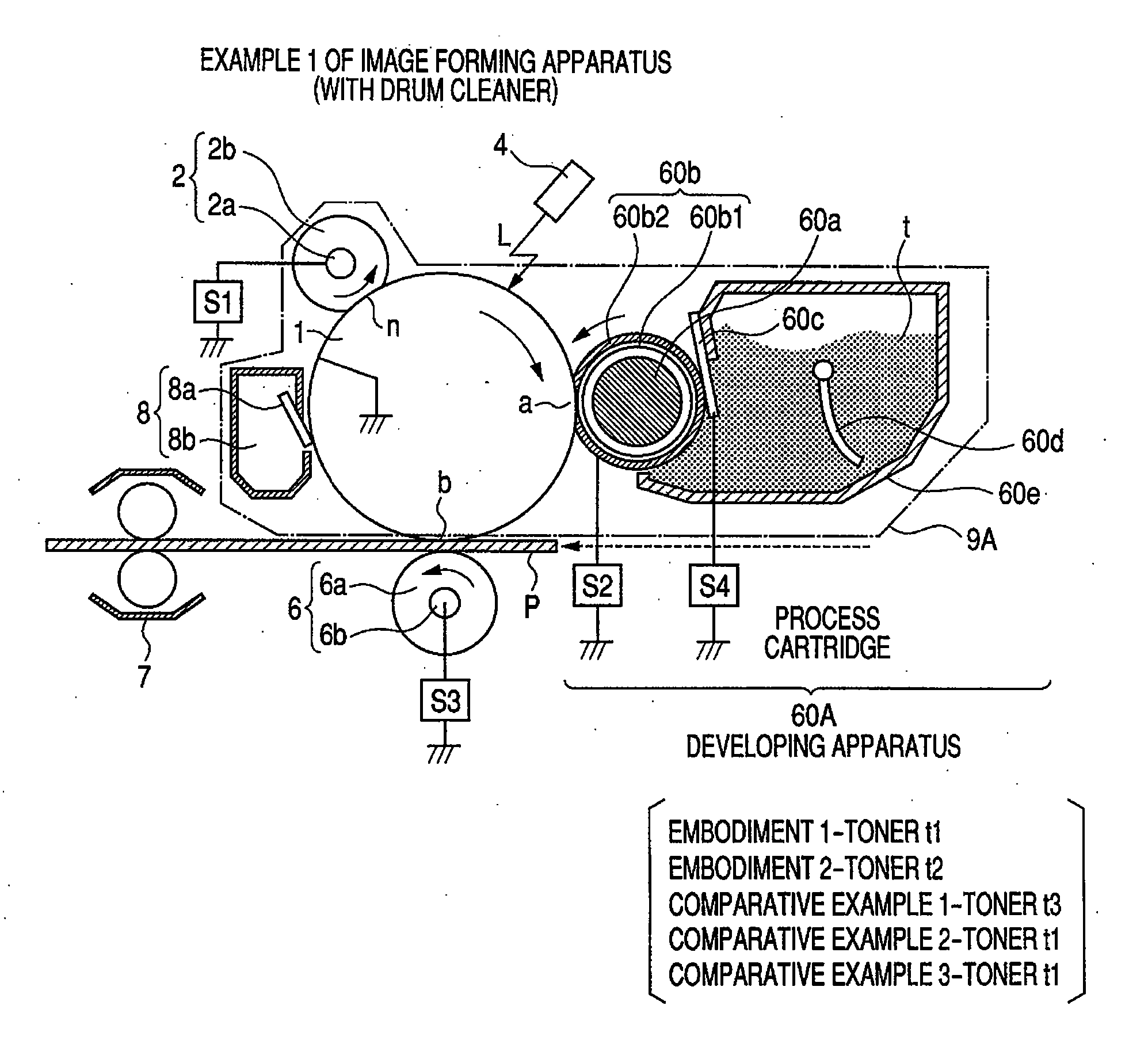
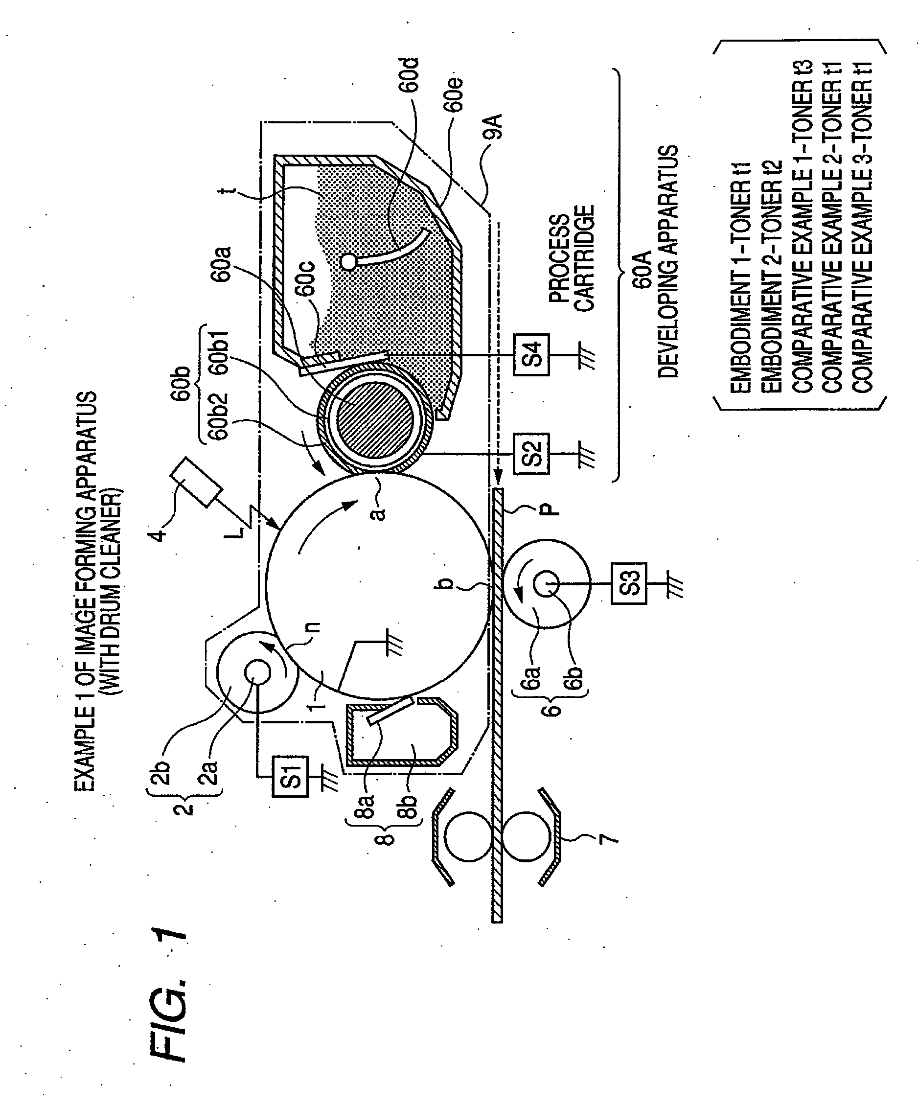
(Example 1 of the Image Forming Apparatus)

[0229] At first, comparison is made about Example 1 of the image forming apparatus (with a drum cleaner).

(1-6a) Comparison with Comparative Examples 4 and 5

[0230] Comparison will first be made with Comparative Examples 4 and 5 in which the blade bias is not applied.

[0231] In Comparative Example 4, in contrast with Embodiment 1, the blade bias is not applied. In a case where the blade bias is not applied, under a high-temperature and high-humidity environment, fog is initially slight, but is aggravated as the number of printed sheets is increased. This is because a proper toner layer thickness and proper charge imparting were not provided by the regulating blade 60c. That is, the abutting position of the regulating portion was made into a pole position, whereby relative to the toner conveying amount by the regulating portion, a toner amount capable of being subjected to proper charge imparting was exceeded. Further, because of the regulat...

example 2

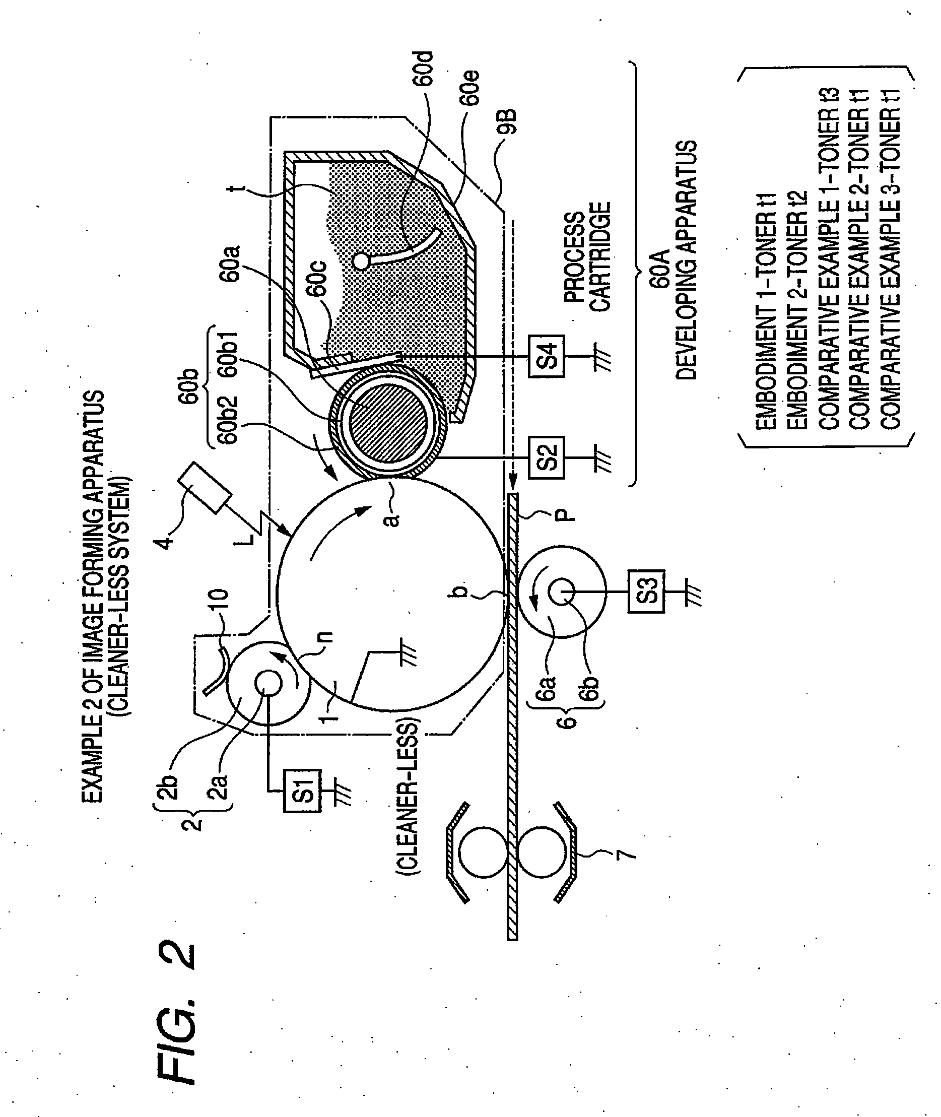
(Example 2 of the Image Forming Apparatus)

[0270] Comparison will now be made about Example 2 of the image forming apparatus (Cleaner-less System).

(1-7a) Cleaner-less Collecting Property and Solid Black Image Fault

[0271] About the toner collecting property in the cleaner-less system, Comparative Examples 6, 7 and 8 which are of the non-contact developing type were bad in the collecting property, while on the other hand, Embodiments 1 and 2 and Comparative Examples 1 to 5 and 10 to 12 were good because of the contact development. However, in Comparative Example 9 which is of the contact developing type, although slightly, a reduction in the collecting property was somewhat seen. It is also conceivable to use a multi-pole magnet roll to improve the supplying and stripping-off property by a rotating magnetic force, but the magnetic force vibrates in the regulating portion and the developing portion and therefore, the toner layer is unstable and thus, the collecting property is consid...


PUM


Abstract

A developing apparatus having a developing sleeve provided with an elastic layer on its surface, and for developing an electrostatic image formed on an image bearing member with a mono-component magnetic toner having a mean degree of circularity of 0.965 or greater, a magnet provided in the developing sleeve, and a blade for regulating the amount of the developer carried on the developing sleeve satisfies the expressions |Br|/|B|≧0.5 and Nsb/(Bs×R)≦0.5, where B [G] is magnetic flux density formed on the surface of the developing sleeve by the magnet at the contact position between the blade and the developing sleeve, Nsb [mm] is the contact width between the blade and the developing sleeve, Br [G] is a component of magnetic flux density B [G] in a direction perpendicular to the surface of the developing sleeve, Bs [rad] is a half value width of the perpendicular component of the magnetic flux density of the nearest one of the magnetic poles of the magnet to the contact position on the surface of the developing sleeve, and R [mm] is the radius of the developing sleeve.

Description

BACKGROUND OF THE INVENTION [0001] 1. Field of the Invention [0002] The invention relates to a developing apparatus for developing an image bearing member with a developer, and more particularly to a developing apparatus of a mono-component developing type in which a developer carrying member contacts with an image bearing member to thereby effect development with a mono-component developer. [0003] This developing apparatus is preferably used as developing means for an image bearing member such as an electrophotographic photosensitive member or an electrostatic recording dielectric member in a process cartridge or an image forming apparatus such as a copying machine or a printer. [0004] 2. Related Background Art [0005] For example, in an electrophotographic image forming apparatus, as a conventional mono-component developing method of developing an electrostatic latent image formed on an electrophotographic photosensitive member as a member to be developed (image bearing member with...

Claims


Application Information

Patent Timeline
Patent Type & Authority Applications(United States)
IPC IPC(8): G03G15/09
CPCG03G15/0812G03G15/0914G03G2215/0634
Inventor HAGIWARA, KAZUNARIOGAWA, KENYAMORIYA, SHUJIKICHIJIMA, NAOTOSHIMIZU, YASUSHIOKUDA, KOICHI
Owner CANON KK
Why Eureka
Try Eureka