Guidewire with superelastic core

a guidewire and superelastic technology, applied in the field of flexible elongated guidewires, can solve the problems of reducing the so-called “torqueability,” or the ability of the guidewire, and achieve the effect of convenient orientation

Inactive Publication Date: 2006-08-03
CORDIS CORP
View PDF29 Cites 119 Cited by
  • Summary
  • Abstract
  • Description
  • Claims
  • Application Information

AI Technical Summary

Benefits of technology

[0010] This guidewire construction results in a flexible distal guidewire portion which can be pre-bent into ...

Problems solved by technology

One disadvantage of guidewires formed from Nitinol is that such guidewires have reduced so-called “torqueabilit...

Method used


Image

  • Guidewire with superelastic core
  • Guidewire with superelastic core
  • Guidewire with superelastic core

Examples


Embodiment Construction

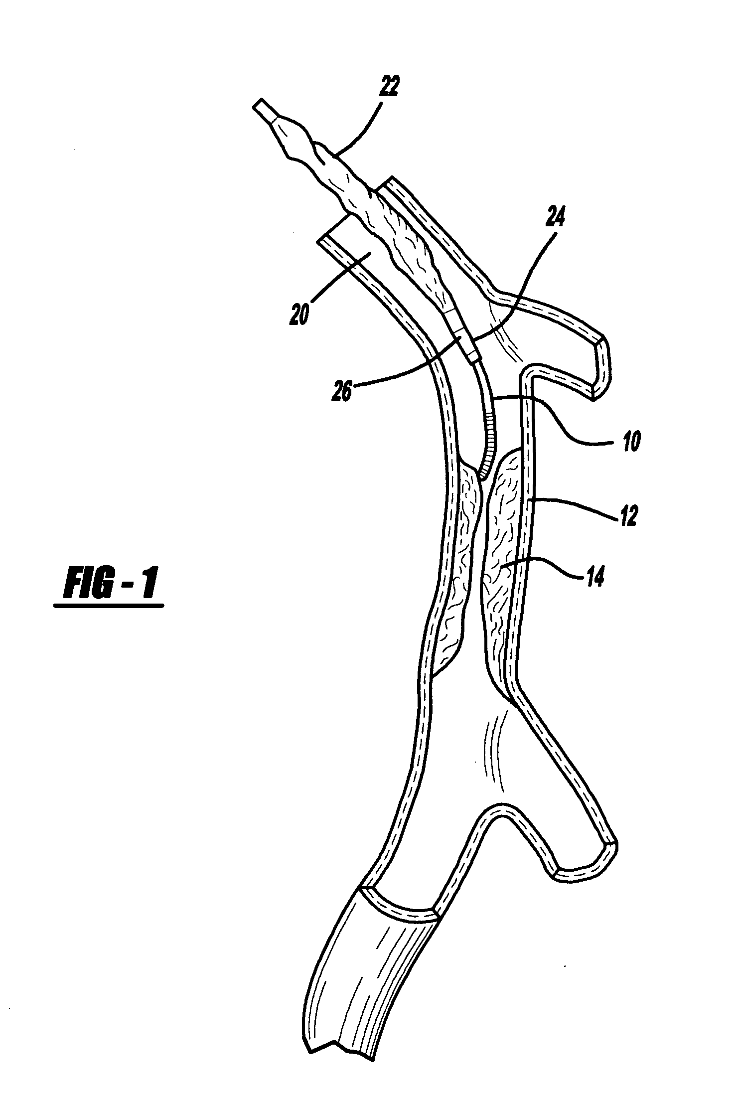
[0017] Turning now to the drawings, FIG. 1 illustrates a distal portion of a flexible, small diameter guidewire 10 that can be guided through a patient's vascular system. A distal end of the guidewire is approaching a region in a blood vessel 12 having an occlusion 14 which has restricted blood flow through the blood vessel 12. The guidewire 10 is long enough to be routed from an entry point of the patient through the vessels of the patient to the obstructed blood vessel region. As the guidewire 10 is inserted along the tortuous path to the obstructed blood vessel region, an attending physician conducting the procedure monitors progress of the guidewire 10 on a fluorographic viewing screen.

[0018] The FIG. 1 depiction illustrates use of a guidewire for routing a balloon catheter 20 to the vicinity of the occlusion 14. The balloon catheter 20 includes a first passageway or lumen which extends from a proximal location outside the patient's body to a distally located balloon 22. A dist...


PUM


Abstract

A medical guidewire including a tapered corewire formed from a superelastic material and a hypotube extending around the outer surface over a portion of the corewire resulting in improved torque characteristics for the guidewire.

Description

BACKGROUND OF INVENTION [0001] 1. Field of the Invention [0002] The present invention relates to a flexible elongated guidewire which may be used to position a catheter within a patient or may be used in a therapeutic procedure, such as to remove an occlusion within a vessel. [0003] 2. Description of the Prior Art [0004] Percutaneous coronary angioplasty (PTA) is a therapeutic medical procedure used to increase blood flow through the coronary artery and can often be used as an alternative to coronary by-pass surgery. An elongated catheter having a deflated balloon at its distal end is guided through a patient's cardiovascular system to the coronary artery of the heart. The balloon is inflated to compress or crack deposits that have accumulated along the inner walls of the coronary artery to widen the artery lumen and increase blood flow. [0005] One prior art technique for positioning the balloon catheter uses an elongated guidewire that is inserted into the patient and passed throug...

Claims


Application Information

Patent Timeline
IPC IPC(8): A61M25/00
CPCA61M25/09A61M2025/09091A61M2025/09133A61M2025/09175
Inventor SCHREINER, JOHN
Owner CORDIS CORP
Why Eureka
Try Eureka