

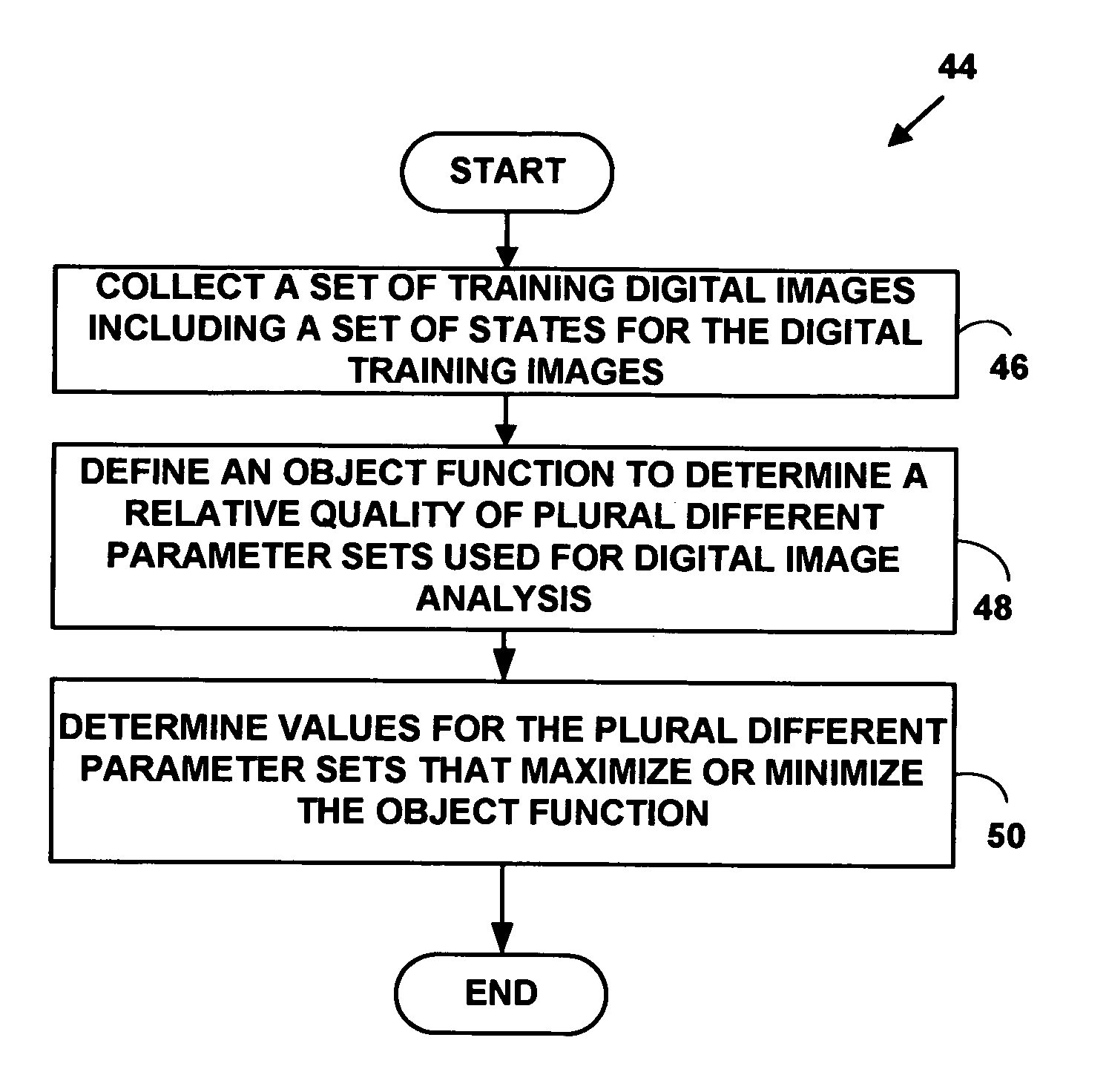
Automated method and system for setting image analysis parameters to control image analysis operations
a technology of image analysis and parameters, applied in the field of digital image processing, can solve the problems of no environmental control of cells, cell death during screening, and toxic new compounds that may look promising at a nucleotide level
- Summary
- Abstract
- Description
- Claims
- Application Information
AI Technical Summary
Problems solved by technology
Method used
Image

Examples
example experimental
Results
[0094] An analysis protocol consisting of parameters that were hand-optimized by an individual with expert domain knowledge was used for comparison with the automated method. An automated process was applied to tune four of the feature calculation parameters as indicated in Table 3 (see, FIG. 3.)
[0095] See FIG. 3 along with the attending discussion, for the meaning of the first three parameters. Target Threshold, is the threshold applied to the mask in the target (e.g. NFκB) channel: if the value of a target image pixel—under either mask—is less than the threshold, that pixel is removed from the mask.
TABLE 3ParameterMinMaxStepRing Distance (a)051Ring Width (b)051Circ Modifier (c)221Target Threshold04095100
[0096] Table 3 includes parameter ranges for the optimization test. The letters following the parameter names refer to their illustrations in FIG. 3. The steps only apply to the exhaustive search method. Step size is unity for all paramters in the GA method. An initial se...
PUM
 Abstract
Description
Claims
Application Information