Stripping assembly

a technology of stout and assembly, which is applied in the direction of stripping-off devices, metal-working devices, manufacturing tools, etc., can solve the problems of spoiled open end of cans, punches may even be damaged, and stout devices

Active Publication Date: 2006-08-10
CROWN PACKAGING TECH
View PDF3 Cites 1 Cited by
  • Summary
  • Abstract
  • Description
  • Claims
  • Application Information

AI Technical Summary

Benefits of technology

[0015] According to another aspect of the present invention, there is provided a method of stripping a can from a punch in a can bodymaker having a stripping assembly with a plurality of fingers and a biasing device for biasing the tips of the fingers into the bore of the bodymaker, the method comprising: enabling the actuator and lifting each finger tip clear of the can carried on the punch against the action of the biasing device when the punch is carrying a can through the bore on the forward stroke; and disabling the actuator when the punch is on the return stroke and allowing the biasing device to close the finger tips to strip the can from the punch; and characterized by enabling the fingers to self-align to the shape of the can on the return stroke of the punch.

Problems solved by technology

Known stripping devices have several drawbacks, particularly when high manufacturing speeds are used.
If excessive pressure is used to strip the can during the return stroke, the open end of the can may be spoiled and the punch may even be damaged.
This device requires the stripping fingers to be formed from magnetically conductive material and is unsuitable for use with cans which are themselves of magnetically conductive material such as steel since any debris arising from the forming process would be attracted to the electromagnet.
Although stripping using air pressure alone has been proposed, such devices have not proved practical at high speeds and a mechanical stripper acting on the edge of the can is still required.

Method used


Image

  • Stripping assembly
  • Stripping assembly
  • Stripping assembly

Examples


Embodiment Construction

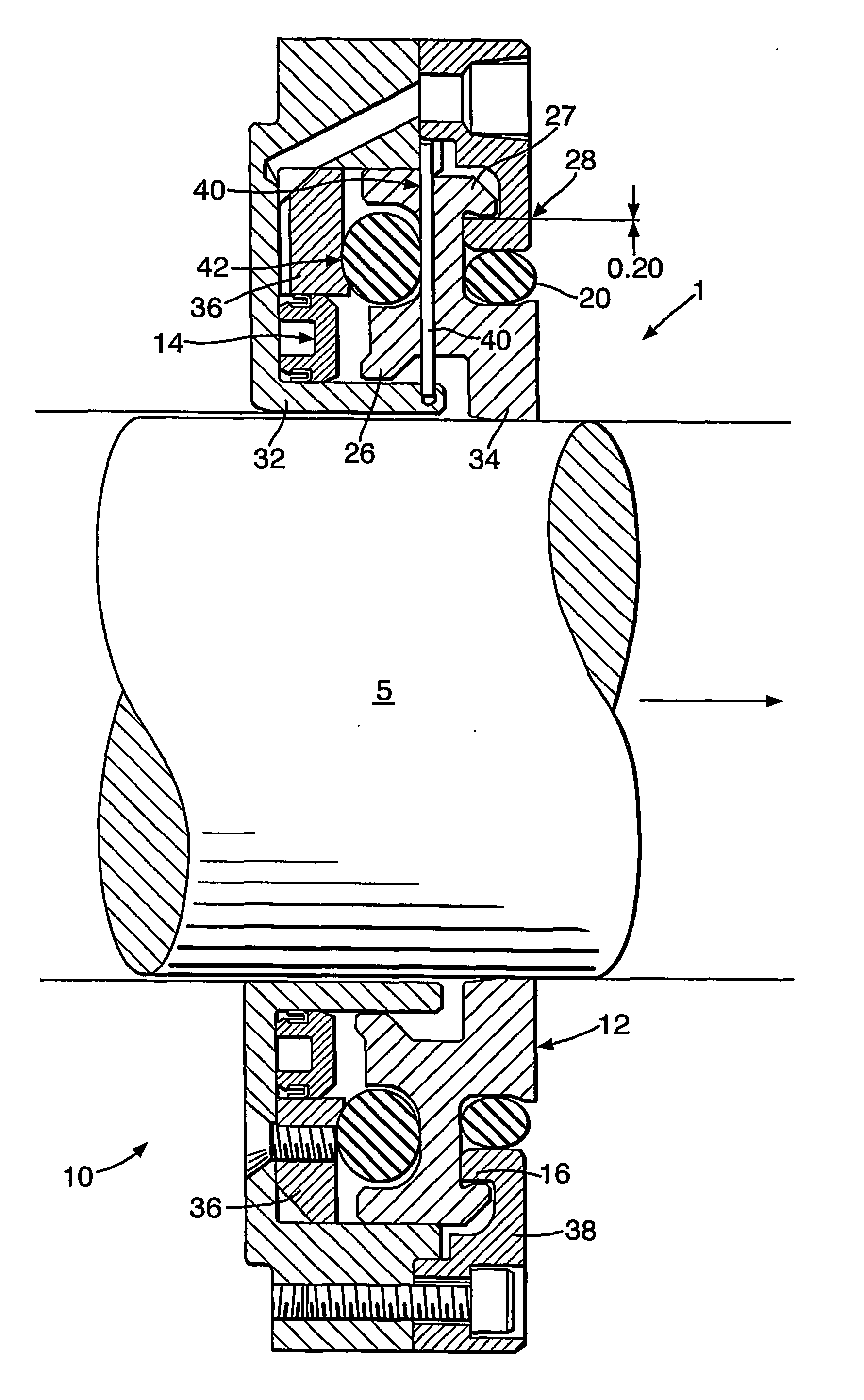
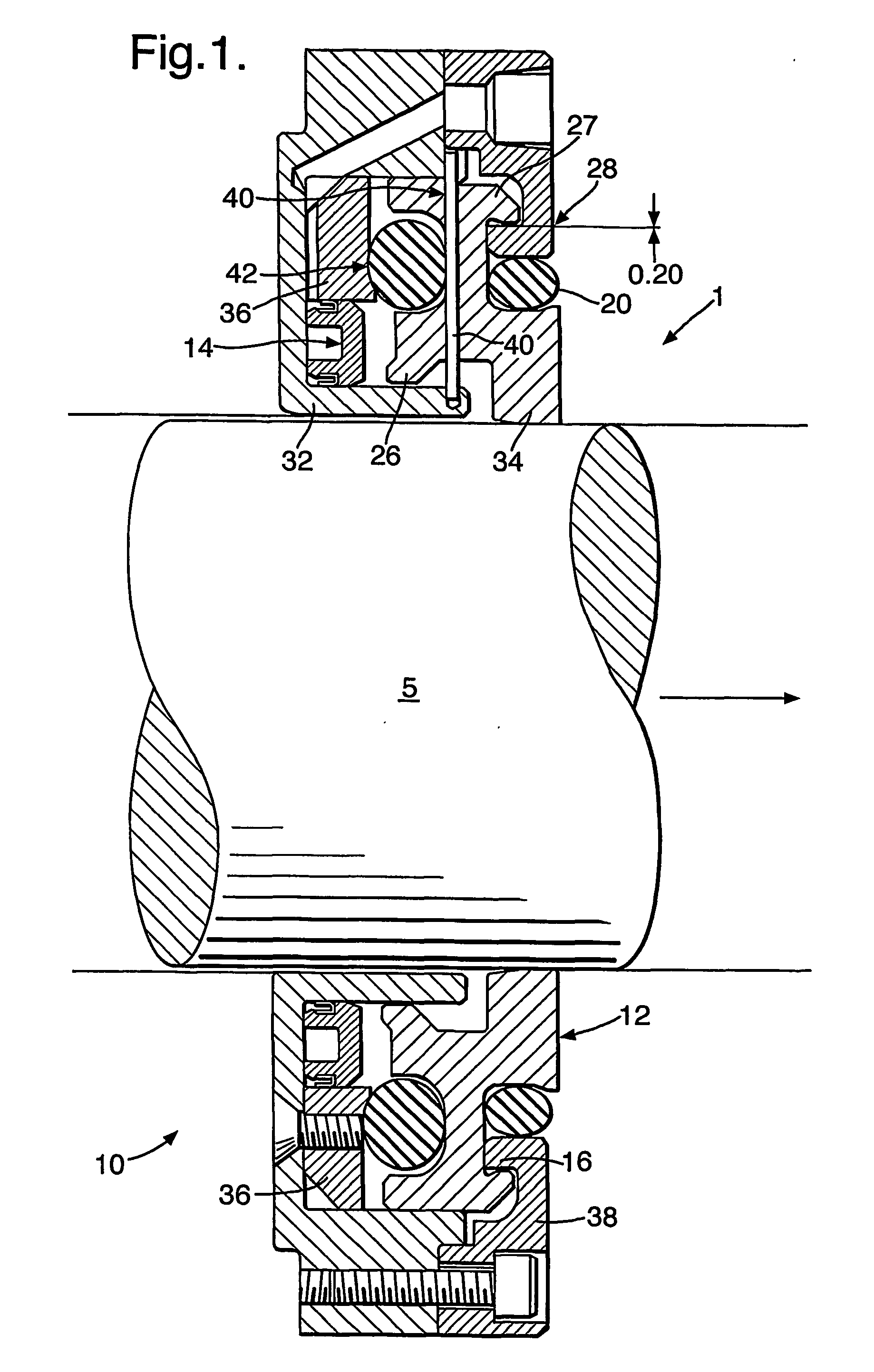
[0020] The stripping assembly 10 is shown in the figures in its “at rest” state. The assembly includes a hollow annular housing 32 defining a central bore 5 of the bodymaker 1. During a draw and wall ironing (DWI) operation, a can is carried on the free end of a punch in the direction of the arrow.

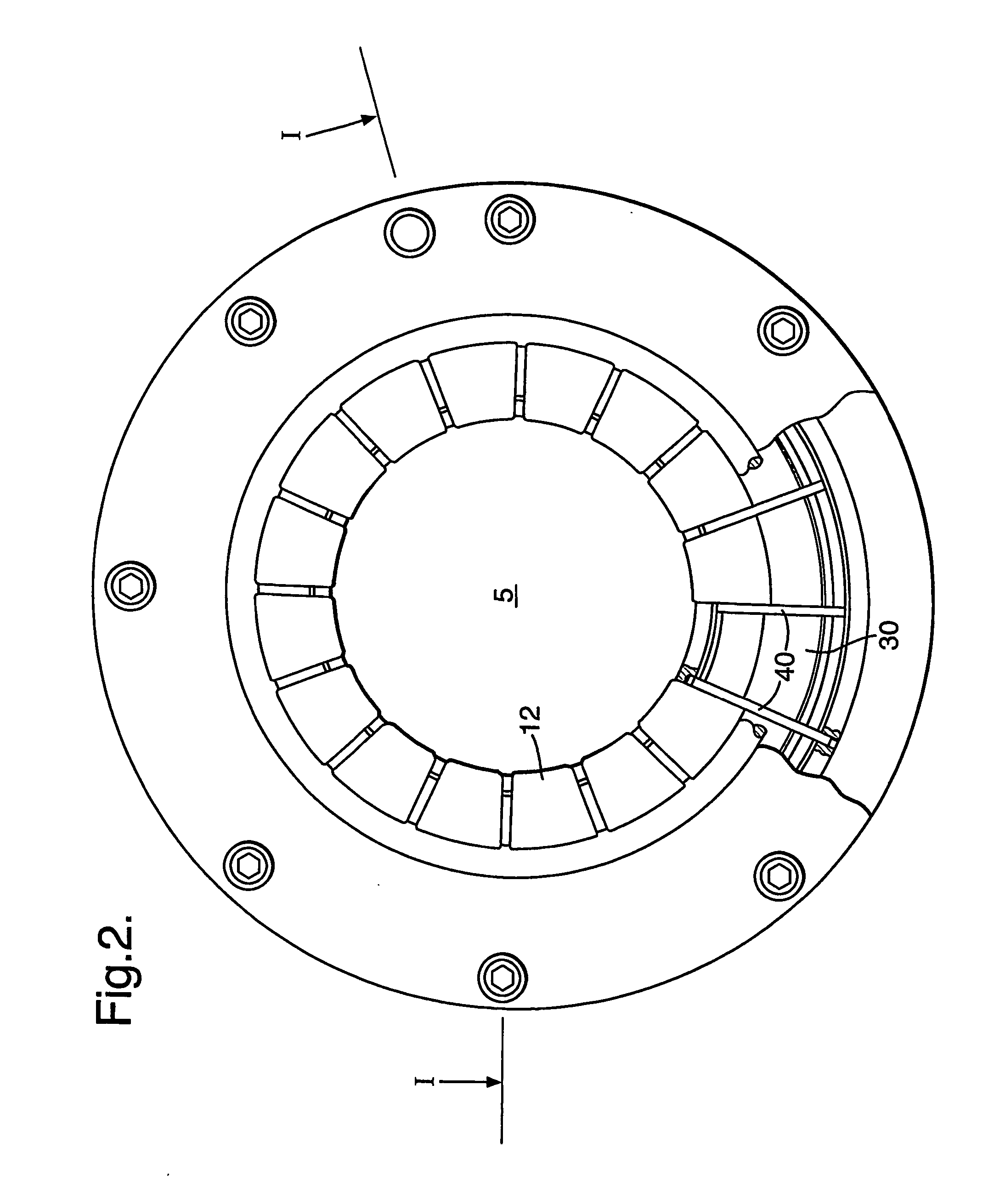
[0021] The housing 32 comprises a pair of complementary upstream and downstream annular shells 36, 38 which are secured face to face to define an annular chamber. A ring of stripper fingers 12 is disposed within the annular chamber of the housing, the tips 34 of the fingers extending from the housing 32 radially inwards into the bore 5. The fingers 12 include a bottom 26 and top 27 portion within the housing 32. The fingers 12 may be of carbide, ceramic or steel, for example. Carbide fingers avoid scoring of the punch on the return stroke if no lubrication is used as, for example, when the can has a polymer coating which could be affected by some lubricants.

[0022] An O-ring 20 is dispose...


PUM


Abstract

A stripping assembly for removal of a can body from a punch in a can bodymaker in which an actuator lifts stripper fingers clear of the can carried on the punch in the forward stroke to avoid damage to the can or can coating. On the return stroke, the actuator piston is disabled so that the fingers close around the punch for stripping the can from the punch.

Description

BACKGROUND OF THE INVENTION [0001] This invention relates to a stripping assembly. In particular, it relates to a stripper for removal of a tubular article, such as a can body, from a close-fitting mandrel on which the article is carried, for example for forming. [0002] Stripping devices are in general use for stripping thin-walled cans from a punch or ram on which such cans have been formed in a “draw and wall-ironing” (“DWI”) process. These strippers typically comprise an annulus of stripping fingers. The annulus is situated within a die assembly such that radially inward ends of the fingers extend into the bore of the assembly through which the punch passes during the DWI process. [0003] The stripper fingers are biased inwardly so that on the forward, can forming, stroke of the punch, the can formed and carried on the punch deflects the stripping fingers against the biasing force as the can moves along the bore through the fingers. After the can has moved axially beyond the finge...

Claims


Application Information

Patent Timeline
Patent Type & Authority Applications(United States)
IPC IPC(8): B21D45/06
CPCB21D45/06
Inventor WOULDS, WILLIAM
Owner CROWN PACKAGING TECH
Why Eureka
Try Eureka