Dispensing device for drinks

a technology for dispensing devices and drinks, which is applied in the direction of liquid transferring devices, applications, instruments, etc., can solve the problems of serious inconvenience and noticeable cooling effects, and achieve the optimization of hygienic and qualitative properties of dispensing devices, increasing the versatility of dispensing devices, and high degree of supply variability.

Inactive Publication Date: 2006-08-10
FRANKE TECH & TRADEMARK LTD
View PDF3 Cites 56 Cited by
  • Summary
  • Abstract
  • Description
  • Claims
  • Application Information

AI Technical Summary

Benefits of technology

[0010] In an especially preferred embodiment of the invention the valve means comprise at least one sliding element that can be moved by a motor and incorporates at least two channels, each of which is associated with at least one particular mode of operation for dispensing the hot drink when in a first position, and when in a second position is connected to the accessory pipeline. By means of such a sliding element, which preferably is constructed as rotary disks, the number and size of “dead spots” (sites inaccessible by rinsing) can be reduced. Moreover, a particularly high degree of variability of the supply and drainage pipelines becomes possible, so that a large number of supply means can be connected to a large number of filling outlets, in various combinations.
[0011] The filling outlets are preferably disposed directly adjacent to the sliding element, so as to ensure extremely short pathways between the valves formed by the sliding element and the filling outlets. This, in turn, optimizes the hygienic and qualitative properties of the dispensing device. Preferably two or more sliding elements are provided, containing channels such that two or more hot drinks can be sent to the same filling outlet, either simultaneously or sequentially, as desired. This increases the versatility of the dispensing device.
[0012] The filling outlets are preferably provided with at least two flow channels, separated in such a way tha

Problems solved by technology

However, this involves many problems, which in particular are solved by the various valve mechanisms that are needed.
For one thing, it turns out that long pipelines are needed, which especially where hot drinks are dispensed is disadvantageous when the dispensing device is not u

Method used


Image

  • Dispensing device for drinks
  • Dispensing device for drinks
  • Dispensing device for drinks

Examples


Embodiment Construction

[0059] In the following description, the same reference numerals are used for identical parts or parts with identical actions.

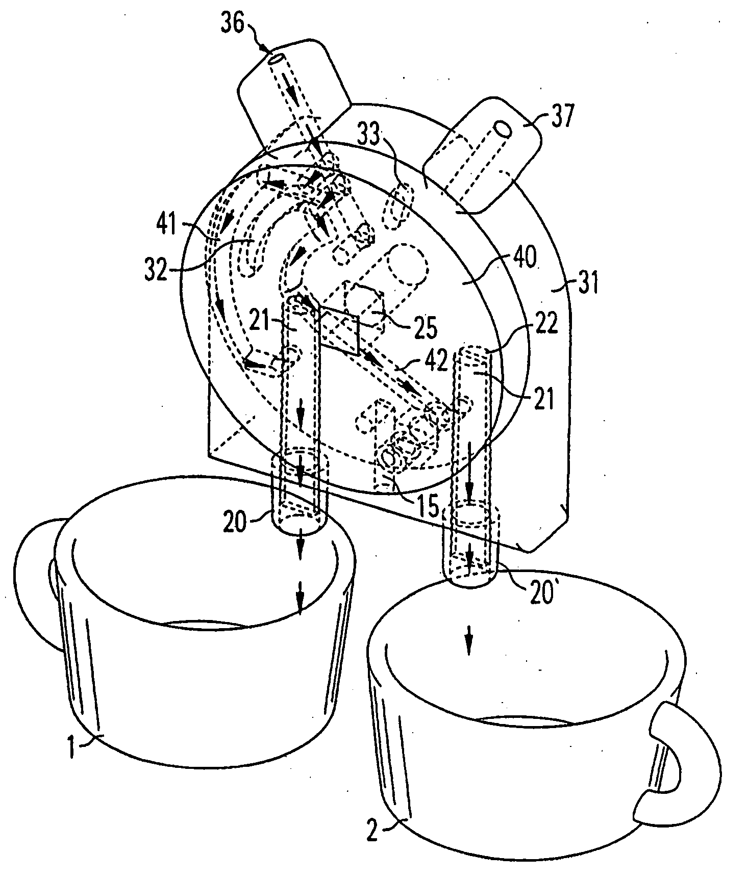
[0060] It should be noted that although the example of a coffee machine shown here is designed to dispense coffee / espresso and milk, it will be clearly evident to a person skilled in the art that the construction shown in principle here can be modified in many ways, in particular for dispensing a greater variety of “drinks” or also other liquid foodstuffs. Therefore when in the following reference is always made to “coffee” and “milk”, this does not restrict the invention to these kinds of drinks. “Coffee” is here intended also to denote in particular espresso, which together with milk and, where appropriate, a foaming means, can be further processed as espresso or latte macchiato.

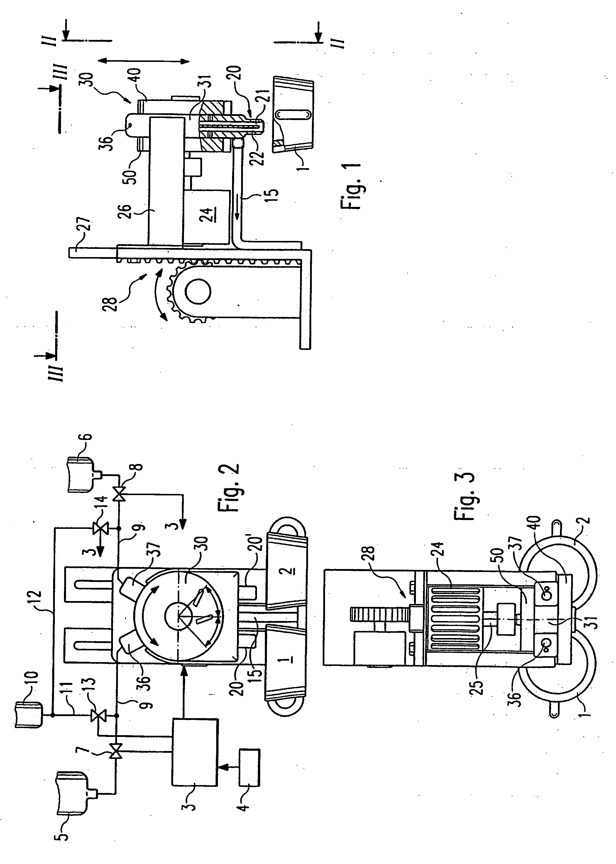
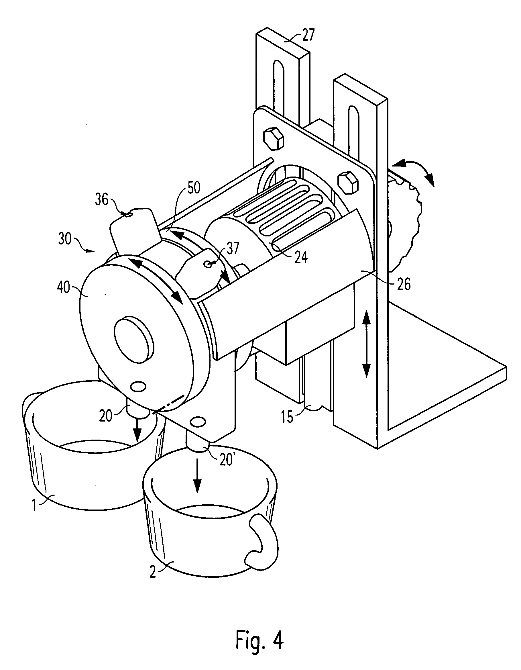
[0061]FIG. 1 shows a major element of a dispensing device in a (partially sectioned) side view; the same device is shown again in FIGS. 2 and 3, in front view together with contro...


PUM


Abstract

Many kinds of dispensing devices for drinks or similar fluid foodstuffs, especially for coffee and/or milk are already known. Said devices comprise supply means for supplying at least two different hot drinks, filling outlets for dispensing hot drinks into at least one cup and valve means for stopping and releasing drink pipelines between the supply devices and the filling devices. According to the invention, in order to improve hygiene and product quality, the valve means are embodied in such a manner that additional pipelines for supplying and/or discharging flushing agents for cleaning, hot water or steam for preheating or other similar fluids, can be connected to the valve means instead of to the drinks pipelines in order to treat the valve means in the areas through which hot drinks flow. As a result, a rinsing process can be automatically controlled between two dispensing steps.

Description

RELATED U.S. APPLICATIONS [0001] Not applicable. STATEMENT REGARDING FEDERALLY SPONSORED RESEARCH OR DEVELOPMENT [0002] Not applicable. REFERENCE TO MICROFICHE APPENDIX [0003] Not applicable. FIELD OF THE INVENTION [0004] The invention relates to a dispensing device for drinks or similar dosable liquid foodstuffs, in particular for coffee and / or milk or similar hot drinks. BACKGROUND OF THE INVENTION [0005] Dispensing devices of this kind are known in many forms. They are used not only in self-service restaurants and canteens, but also in normal hotels and the like, with the result that fewer service personnel are needed behind the counter. [0006] So that on one hand several different drinks, or also mixed drinks, can be dispensed while on the other hand it is not necessary to employ a large number of “specialized” dispensing devices, dispensing devices are designed so that they can be switched into different modes. However, this involves many problems, which in particular are solve...

Claims


Application Information

Patent Timeline
IPC IPC(8): A23C3/02B67D5/06B67D1/07A23L2/00A47J31/44A47J31/60B67D7/06
CPCA47J31/4482A47J31/60
Inventor GREIWE, HANSDIETER
Owner FRANKE TECH & TRADEMARK LTD
Why Eureka
Try Eureka