Defibrillator insertion device and method

a technology of insertion device and insertion device, which is applied in the field of insertion device and method of febrillator, can solve the problems of difficult to make incisions only as large, require a degree of experience and skill, and less precise incisions

Inactive Publication Date: 2006-08-10
TEAM BROWN ENTERPRISES
View PDF11 Cites 50 Cited by
  • Summary
  • Abstract
  • Description
  • Claims
  • Application Information

AI Technical Summary

Problems solved by technology

These subsequent incisions are less precise than the initial incision and require a degree of experience and skill to prevent unnecessary trauma, as it is difficult to make the incisions only as large as necessary to accommodate the device.
This insertion method places stress on the connection between the leads of the device and the device itself as the leads are being pulled by the tissue passing over the device.

Method used


Image

  • Defibrillator insertion device and method
  • Defibrillator insertion device and method
  • Defibrillator insertion device and method

Examples


Embodiment Construction

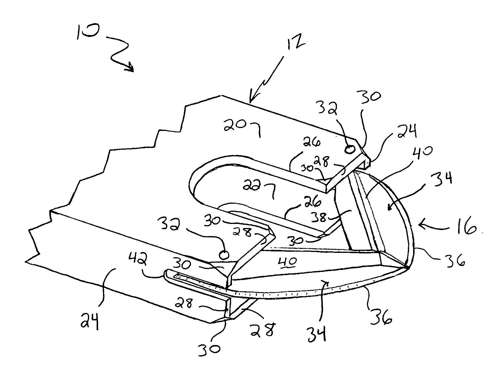
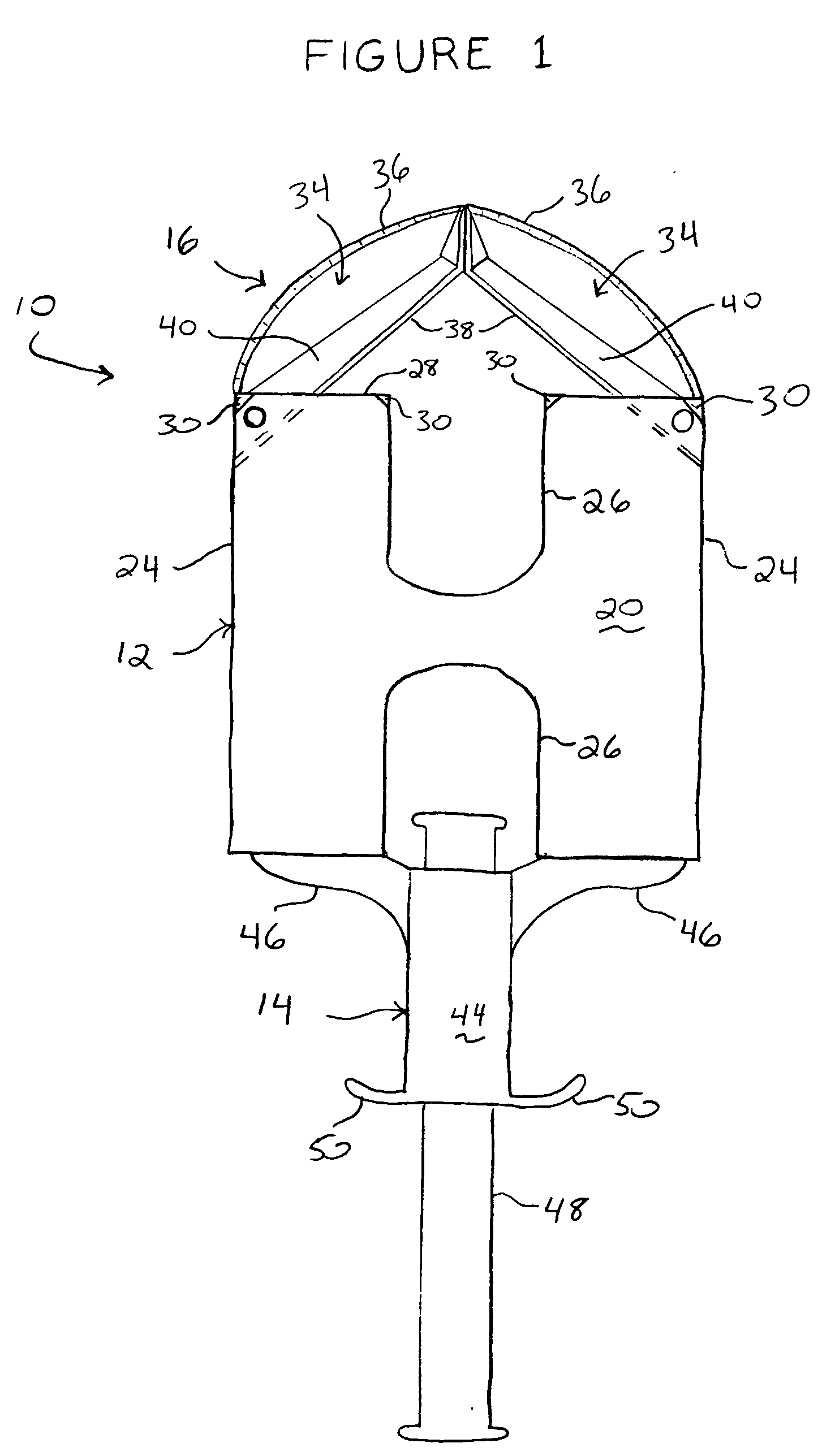
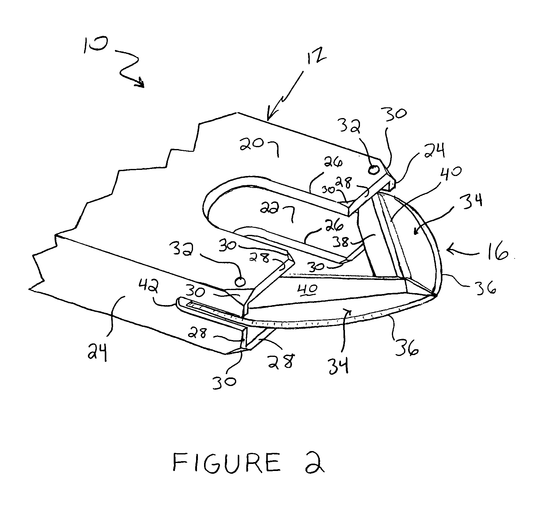
[0013] Referring now to the Figures, there is shown a delivery device 10 of the present invention. The delivery device 10 generally includes a body 12, a handle 14 at a proximal end of the body 12, and a blade assembly 14 at a distal end of the body 12.

[0014] The body 12 defines a compartment that is sized to receive an ICD 18 (FIG. 3) and is more specifically defined by an upper wall 20, a lower wall 22 and a pair of opposed sidewalls 24. The upper and lower walls 20 and 22 are shown as including optional cutouts 26. The cutouts 26 facilitate easy cleaning, if the device 10 is to be constructed as a reusable instrument, and also prevent the introduction of an air bubble into the implantation site.

[0015] Distal edges 28 of the walls 20, 22, and 24 define a distal opening of the compartment. As shown in FIG. 2, the distal edges 28 include chamfered corners 30 to prevent trauma to surrounding tissue during insertion. It is also envisioned to round the distal edges 28. The body 12 al...


PUM


Abstract

A device is provided that may be used to implant a subcutaneous device such as an ICD or a pacemaker. The device includes a body defining a compartment for holding the ICD during insertion and a blade assembly that cuts a path toward the targeted implantation site. A handle assembly including a plunger is used to expel the ICD from the compartment once the targeted implantation site has been reached.

Description

BACKGROUND OF THE INVENTION [0001] The device of the present invention relates to a device that can be used to simply and safely insert a subcutaneous device such as an implantable defibrillator. Such devices shall hereinafter be referred to broadly as ICDs (Implantable Cardiac Devices). ICDs are typically flat devices, about the size of soap bars, which are implanted in the chest on the patient's left side just up under the collarbone. [0002] Typical implantation procedures involve using a local anesthetic at the insertion site and a narcotic known as a “twilight” sedative, which relaxes the patient. A first incision is made through the skin, and subsequent, deeper incisions are made in order to provide a pocket into which the device may be placed. These subsequent incisions are less precise than the initial incision and require a degree of experience and skill to prevent unnecessary trauma, as it is difficult to make the incisions only as large as necessary to accommodate the devi...

Claims


Application Information

Patent Timeline
Patent Type & Authority Applications(United States)
IPC IPC(8): A61B19/00
CPCA61B17/320016A61B17/3211A61B17/3468A61N1/3956
Inventor BROWN, WARD M.
Owner TEAM BROWN ENTERPRISES
Why Eureka
Try Eureka