UAV arresting hook for use with UAV recovery system

a technology for uav recovery and hooks, which is applied in the direction of arrest hooks, micro-sized aircraft, transportation and packaging, etc., can solve the problems of difficult to safely land a uav on the deck of a ship, the difficulty of recovering a uav, and the difficulty of regaining a uav on the ship deck

Inactive Publication Date: 2006-08-10
LOCKHEED MARTIN CORP
View PDF13 Cites 42 Cited by
  • Summary
  • Abstract
  • Description
  • Claims
  • Application Information

AI Technical Summary

Benefits of technology

[0014] In the illustrative embodiment, the rotation is accomplished as follows. The arm of the arresting hook is rotatably coupled to the rotation block such that the arm is free to rotate about its longitudinal axis. A torsion spring, which is located on the rotation block, is attached to the arm. This creates a spring bias that urges the arm to rotate about its longitudinal axis. The arm is prevented from rotating in this fashion while it's held flush against the underside of the UAV. Once released, wherein one end of the arm falls away from the underside of the UAV, the arm is free to rotate about its longitudinal axis, and does so as a consequence of the bias provided by the spring.
[0015] The arm is, therefore, provided with two rotational degrees of freedom. One of the degrees of freedom enables an end of the arm to drop away from the fuselage of the UAV and the other enables the arm to rotate about its own longitudinal axis to re-orient the latches so that they are properly positioned to snag the arresting line. In the illustrative embodiment, it is the rotation block that provides these two rotational degrees of freedom.
[0016] In the illustrative embodiment, the arresting hook includes latches as opposed to simple hooks because it has been observed that when the arm is flown into the arresting line of a UAV recovery system, the arm tends to “bounce” off of the line. The latch (or other such closure mechanism) prevents this from occurring. That is, once captured by a latch, any bounce that is experienced will not decouple the arm from the arresting line.

Problems solved by technology

Recovery is considerably more challenging, however, when the UAV is operating at sea.
Due to the constant sway, roll, pitch and yaw of a ship at sea, it is quite difficult to safely land a UAV on the deck of a ship.
In fact, deck landings are rarely attempted.
This technique has its own drawbacks, including a reasonable likelihood of damage to the UAV and some risk to the recovery crew.
One drawback is that the apparatus disadvantageously requires a substantial amount of deck area.
A second drawback is that a relatively labor-intensive untangling operation is required to free the UAV from the net.
Furthermore, the relatively abrupt stop of a UAV in the recovery net can damage its fragile wings.

Method used


Image

  • UAV arresting hook for use with UAV recovery system
  • UAV arresting hook for use with UAV recovery system
  • UAV arresting hook for use with UAV recovery system

Examples


Embodiment Construction

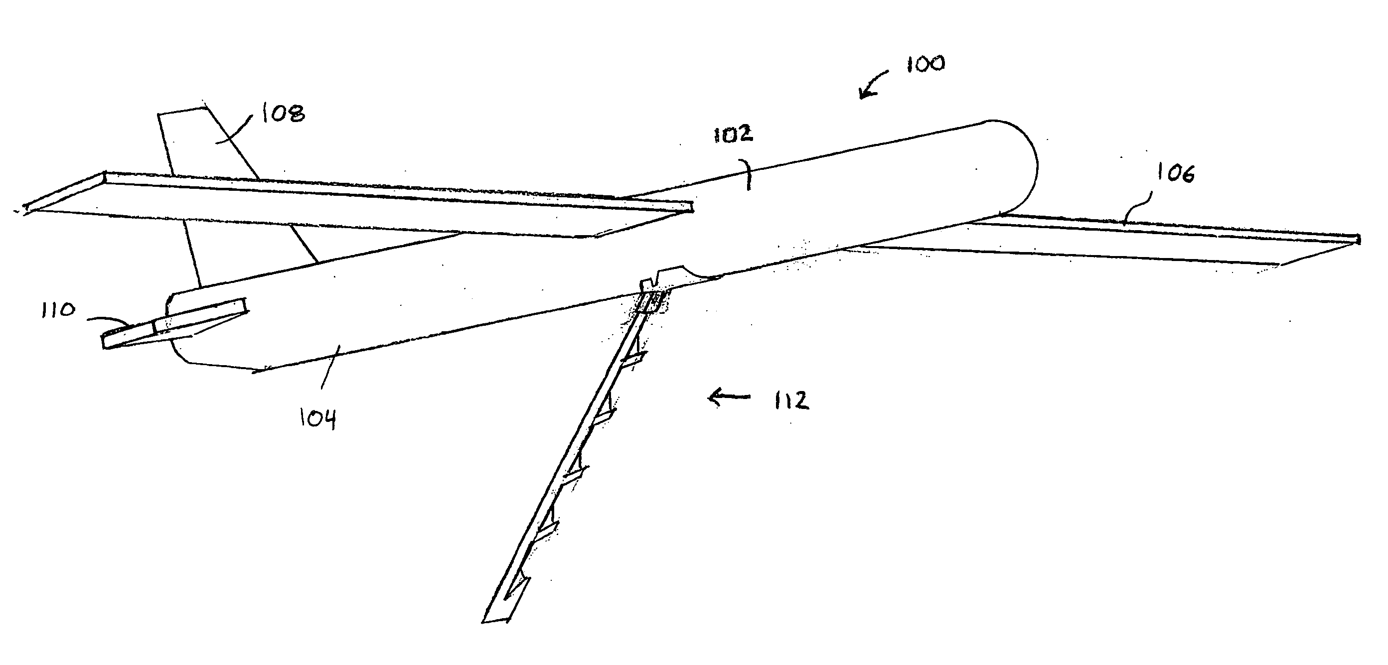
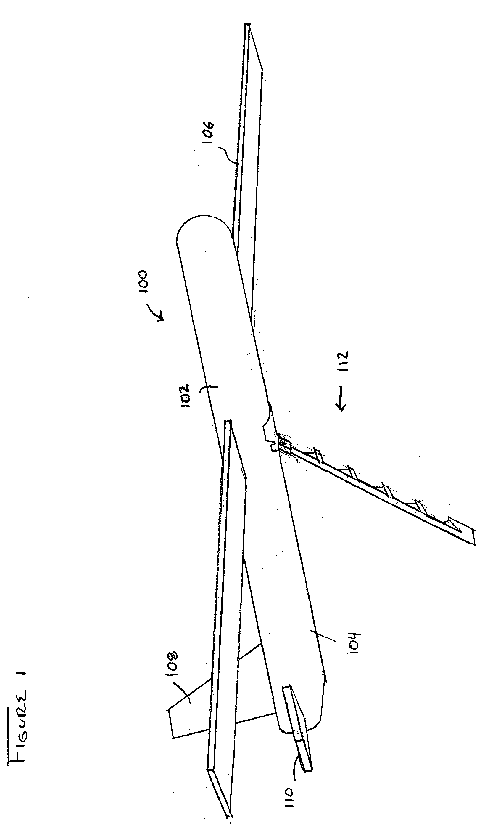
[0025]FIG. 1 depicts UAV 100 with arresting hook 112 in accordance with the illustrative embodiment of the present invention. In FIG. 1, arresting hook 112 is in a deployed position in preparation for snagging the arresting line (not depicted) of a UAV recovery system.

[0026] UAV 100 includes fuselage 102, wings 106, vertical stabilizer 108, horizontal stabilizers 110, and arresting hook 112. The arresting hook is coupled to underside 104 of fuselage 102.

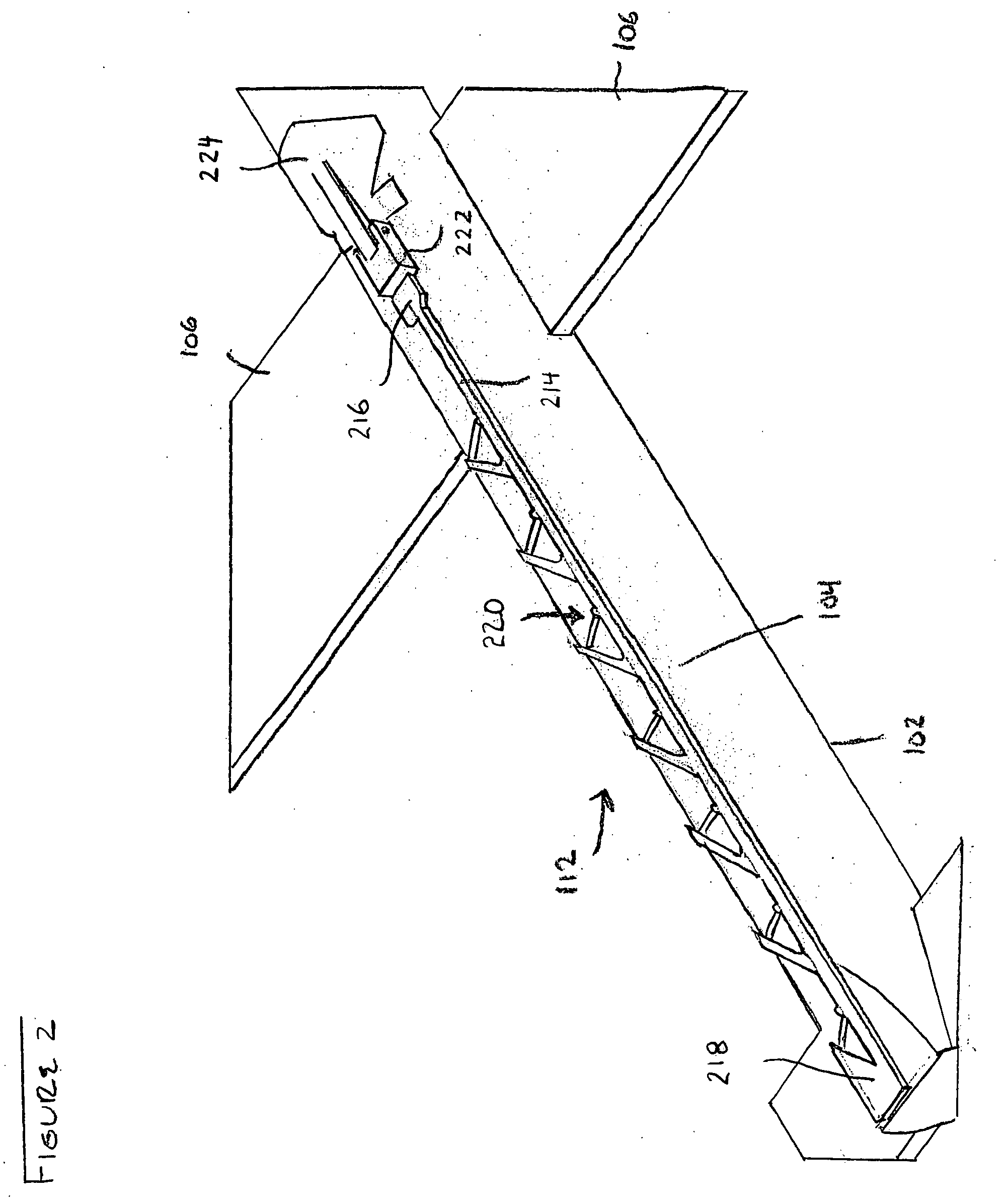
[0027]FIG. 2 depicts the underside of UAV 100 and shows further detail of arresting hook 112. In FIG. 2, arresting hook 112 is in a stowed position. Arresting hook 112 is coupled to underside 104 of fuselage 102 via mounting bracket 224.

[0028] Arresting hook 112 comprises arm 214, a plurality of latches 220, and rotation block 222, structurally interrelated as shown. In the illustrative embodiment, arresting hook 112 is coupled to fuselage 102 at about the midpoint between the nose and tail of UAV 100.

[0029] Front end 216 of arm ...


PUM


Abstract

A UAV arresting hook is disclosed. The arresting hook facilitates the capture of a UAV via a UAV recovery system. In the illustrative embodiment, the arresting hook has a rotation block, an arm, and a plurality of latches that are disposed on the arm. The arm is coupled to the UAV via the rotation block, which provides two rotational degrees of freedom to the arm. In a stowed position, the arm is flush against the surface of the UAV. To deploy the arm, a free end of the arm is rotated away from the surface of the UAV. The arm is additionally biased to rotate about its longitudinal axis as it rotates away from the surface of the UAV. This rotation positions the latches to capture an arresting line that is part of a UAV recovery system.

Description

FIELD OF THE INVENTION [0001] The present invention relates to systems for retrieving unmanned aerial vehicles (“UAVs”). BACKGROUND OF THE INVENTION [0002] The UAV is now widely used for reconnaissance. Characteristically small, inexpensive, and pilot-less (i.e., unmanned cockpit), the UAV is ideal for that purpose. [0003] Notwithstanding its low cost, the UAV is not considered to be a disposable item; recovery is at least attempted after each mission. Recovery is relatively straightforward when the UAV is operating over land. In such situations, the UAV is simply brought down on a makeshift landing field. Recovery is considerably more challenging, however, when the UAV is operating at sea. Due to the constant sway, roll, pitch and yaw of a ship at sea, it is quite difficult to safely land a UAV on the deck of a ship. In fact, deck landings are rarely attempted. [0004] One alternative to the deck landing is the water “landing,” wherein a UAV is simply ditched in the sea. This techni...

Claims


Application Information

Patent Timeline
Patent Type & Authority Applications(United States)
IPC IPC(8): B64C3/38
CPCB64C25/68B64C39/028B64C2201/182B64C2201/127B64F1/02B64C2201/104B64F1/029B64U30/10B64U2101/30B64U70/30
Inventor SNEDIKER, JOHNWATTS, MICHAEL A.CORBOY, GRANT W.
Owner LOCKHEED MARTIN CORP
Why Eureka
Try Eureka