Broadband microwave amplifier

a microwave amplifier and wideband technology, applied in the field of electrical and electronic circuits and systems, can solve the problems of limited operation bandwidth, dc power, and lower efficiency of class-e amplifiers, and achieve the effect of wide bandwidth

Active Publication Date: 2006-08-10
PACKAGING DYNAMICS OPERATING +1
View PDF15 Cites 9 Cited by
  • Summary
  • Abstract
  • Description
  • Claims
  • Application Information

AI Technical Summary

Problems solved by technology

The choice of technology, design methodology and manufacturing cycle time are major cost contributors in these systems.
Other classes of amplifiers such as class A, A / B and C, operate as a current-source with overlapping voltage & current waveforms and hence dissipate DC power leading to a lower efficiency.
In any event, the maximum efficiency of Class-E amplifiers (i.e. the ratio of the RF output power to the DC input power) and its bandwidth of operation are limited by the tuned loads thereof.
The limitation is due to the fact that presence of the tuned load results in a very narrow operational bandwidth for the amplifier.

Method used


Image

  • Broadband microwave amplifier
  • Broadband microwave amplifier
  • Broadband microwave amplifier

Examples


Embodiment Construction

[0021] Illustrative embodiments and exemplary applications will now be described with reference to the accompanying drawings to disclose the advantageous teachings of the present invention.

[0022] While the present invention is described herein with reference to illustrative embodiments for particular applications, it should be understood that the invention is not limited thereto. Those having ordinary skill in the art and access to the teachings provided herein will recognize additional modifications, applications, and embodiments within the scope thereof and additional fields in which the present invention would be of significant utility.

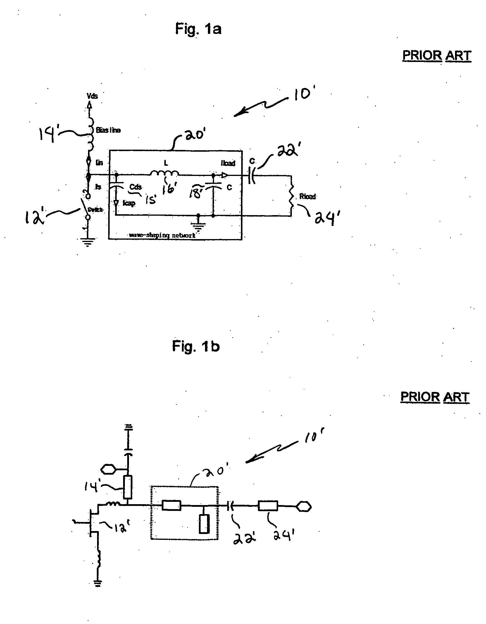
[0023]FIG. 1a is a simplified schematic diagram of an ideal discrete component implementation of a typical Class-E load in accordance with conventional teachings. As shown in FIG. 1a, a typical Class-E amplifier represented by a switch 12′ is coupled to a source Vds via an inductive bias line 14′. The switch 12′ is coupled to a resistive load 24′...


PUM


Abstract

A Class-E load circuit topology suitable for switching mode Power Amplifiers (PAs). The inventive load includes a shunt inductive element coupled to an output of said amplifier; a series inductive element coupled to said output of said amplifier; and a series capacitive element coupled to said series inductive element. In the illustrative embodiment, the inventive load is operable at frequencies in the range of 8-10 GHz and the shunt inductive element is an inductive bias line for said amplifier. The invention enables an advantageous Class-E amplifier design comprising an input matching network; an active device coupled to the input matching network and a load coupled to the active device and implemented in accordance with the present teachings. Also disclosed is a method for designing a load for use with a Class-E amplifier including the steps of: providing a lumped equivalent circuit representation of the load; optimizing the lumped equivalent circuit representation of the load to achieve near ideal current and voltage operational characteristics over a predetermined frequency range using a time domain simulation; transforming the optimized lumped equivalent circuit representation of the load to a distributed circuit representation; and optimizing the distributed circuit representation of the load to achieve near ideal current and voltage operational characteristics over a predetermined frequency range using a time domain simulation.

Description

BACKGROUND OF THE INVENTION [0001] 1. Field of the Invention [0002] The present invention relates to electrical and electronic circuits and systems. More specifically, the present invention relates to microwave Class E power amplifiers. [0003] 2. Description of the Related Art [0004] For a variety of commercial and military applications, highly efficient microwave and radio frequency (RF) power amplifiers are needed. Typical applications include wireless local area networks, cell phones and telecommunication systems as well as advanced airborne active phased array radar systems. The choice of technology, design methodology and manufacturing cycle time are major cost contributors in these systems. Switching mode, Class-E, high-efficiency power amplifiers are useful for these and other applications inasmuch as these amplifiers limit the power and associated cooling costs thereof. A Class-E amplifier is part of the “switching mode amplifiers” such as class D, E, F, etc. In these types ...

Claims


Application Information

Patent Timeline
Patent Type & Authority Applications(United States)
IPC IPC(8): H03F3/217
CPCH03F3/2176H03F2200/03H03F3/217H03H7/38
Inventor TAYRANI, REZAGORDON, JONATHAN D.
Owner PACKAGING DYNAMICS OPERATING
Why Eureka
Try Eureka