Liquid jetting device

a technology of liquid ejecting device and liquid ejector, which is applied in the direction of printing, etc., can solve the problems of large space occupation of total ink supply tubes, large number of assembling steps, and ineffective cost reduction, and achieves the effect of reducing labor intensity, reducing labor intensity, and simplifying the construction of sub tanks

Inactive Publication Date: 2006-08-10
SEIKO EPSON CORP
View PDF7 Cites 7 Cited by
  • Summary
  • Abstract
  • Description
  • Claims
  • Application Information

AI Technical Summary

Benefits of technology

[0007] This invention is developed by focusing the aforementioned problems in order to resolve them effectively. The object of this invention is to provide a liquid ejecting apparatus wherein construction of a sub tank is much simplified and wherein absorbing function of pressure fluctuation in the sub tank is much improved.

Problems solved by technology

If independent sub tanks are mounted on the carriage for the respective kinds of ink, the number of kinds of components and the number of the components are large depending on the number of the kinds of ink, which is disadvantageous for the reduction of cost.
In addition, the number of assembling steps is also large.
Furthermore, if each ink supplying tube is connected to each sub tank, the total ink supplying tubes takes a large space, and connecting operations thereof are much troublesome.

Method used


Image

  • Liquid jetting device
  • Liquid jetting device
  • Liquid jetting device

Examples


first embodiment

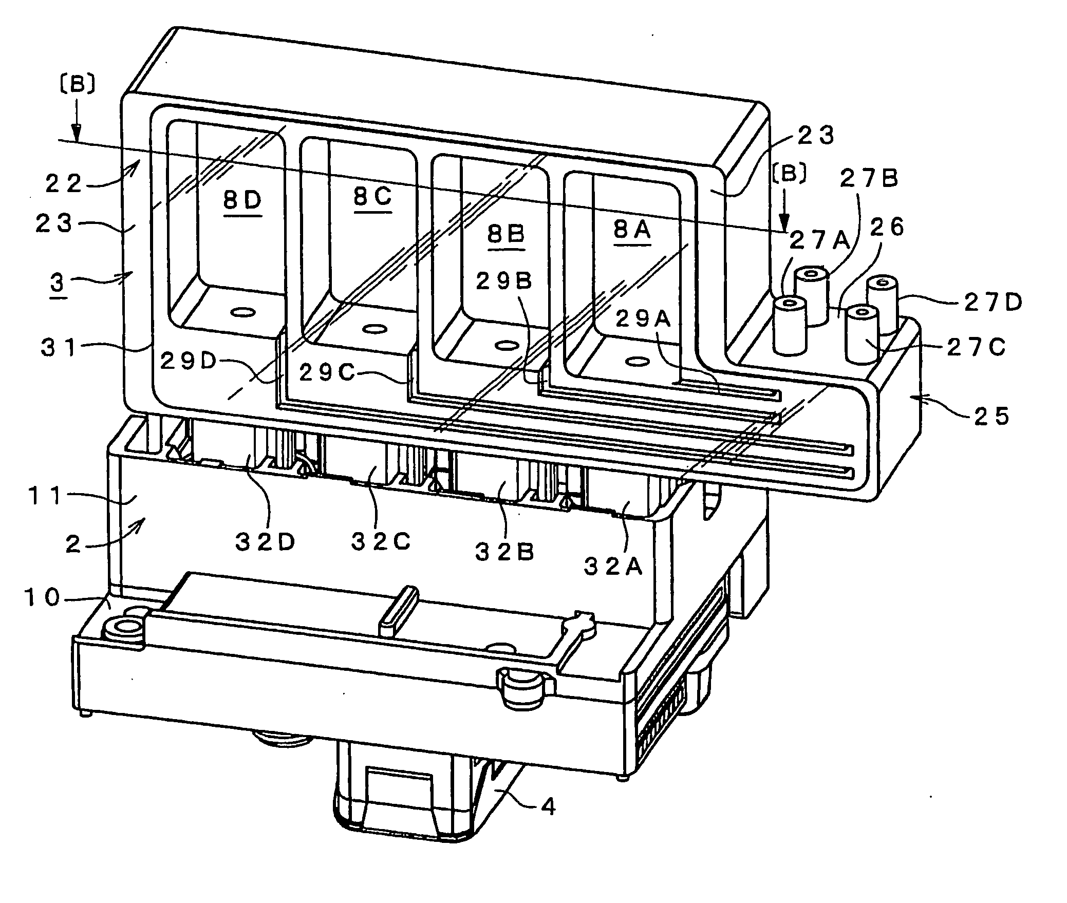
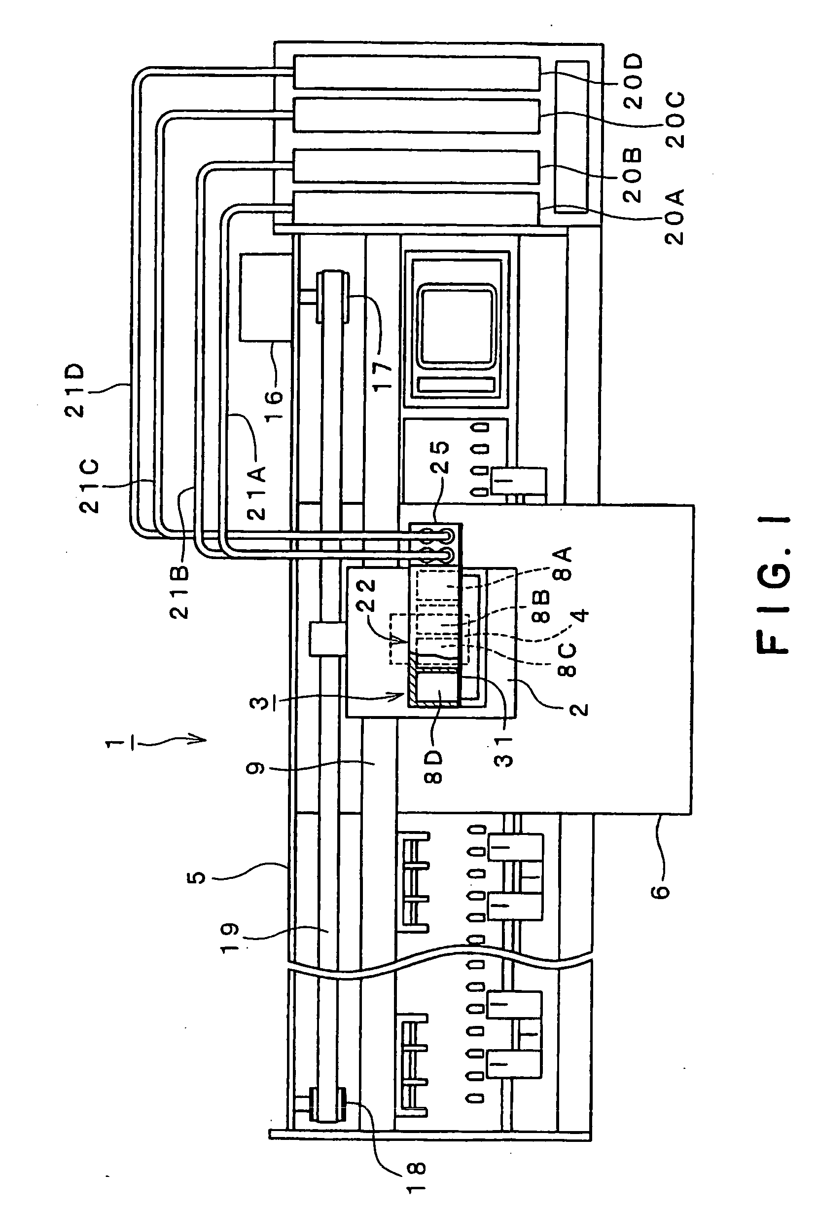
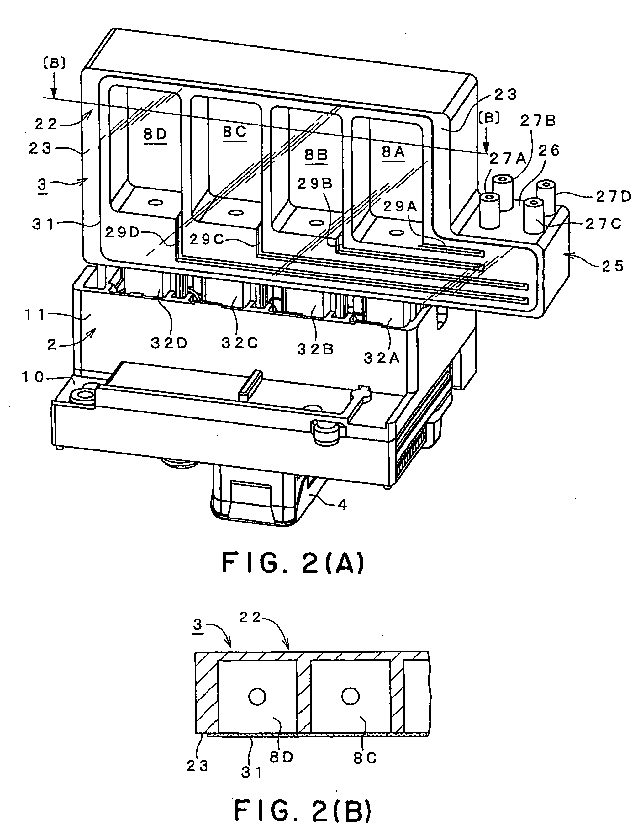
[0052]FIG. 1 is a schematic plan view of an ink-jetting printer 1 (hereinafter, referred to as printer 1) that is an ink-jetting recording apparatus as a first embodiment according to the invention. FIG. 2(A) is a perspective view of a carriage 2 seen from an obliquely upside thereof. FIG. 2(B) is a sectional view taken along a line B-B of FIG. 2(A). FIG. 3(A) is a longitudinal sectional view of the carriage 2 and a sub tank 3. FIG. 3(B) is a sectional view taken along a line B-B of FIG. 3(A). FIG. 3(C) is a sectional view taken along a line C-C of FIG. 3(A).

[0053] As shown in FIG. 1, the printer 1 is mainly formed by the carriage 2 and a printer main body 5, the sub tank 3 and a recording head 4 being mounted on the carriage 2. In the printer main body 5, provided are a head scanning mechanism that causes the carriage 2 to reciprocate in a main scanning direction, a paper feeding mechanism that feeds a recording paper 6 in a paper-feeding direction, a recovering mechanism that reco...

second embodiment

[0073] Next, FIG. 4 is a perspective view of a carriage in an ink-jetting recording apparatus of a second embodiment according to the invention.

[0074] In the second embodiment, mounting posture of the sub tank 3 is set in such a manner that the edge surface 23 is substantially horizontal. Then, the cylindrical needle-connection parts, not shown, are arranged on a side opposite to the elastic sheet 31. The other structures are substantially the same as the first embodiment. The same parts are represented by the same numeral signs, and explanation thereof is omitted.

[0075] When the above structure is adopted, a depth of the ink storing rooms 8A, 8B, 8C, 8D in a perpendicular direction with respect to the elastic sheet 31 may be made smaller, so that dimensions of the sub tank 3 in the perpendicular (vertical) direction may be made small. Thus, an occupancy space required near the carriage 2 may be reduced.

third embodiment

[0076] Next, FIGS. 5(A) to 5(C) are views showing a sub tank in a third embodiment according to the invention.

[0077] In the present embodiment, the ink-storing-room openings are also open at a flat reverse edge surface 34, oppositely to the edge surface 23. A second elastic sheet 31′ is jointed to the reverse edge surface 34. The other structures are substantially the same as the first embodiment. The same parts are represented by the same numeral signs, and explanation thereof is omitted.

[0078] In the above structure, the respective ink storing rooms 8A, 8B, 8C, 8D can have the elastic sheets 31, 31′ at the two surfaces. Thus, effective areas of the elastic sheets 31, 31′ may be made as large as possible, so that a volume of each liquid storing room 8A, 8B, 8C, 8D may be made as small as possible. Thus, the sub tank 3 may be made more compact, which is effective in reducing required space and cost.


PUM


Abstract

The present invention is a liquid ejecting apparatus including: a carriage that reciprocates in a main scanning direction; a liquid ejecting head mounted on the carriage, having a plurality of head-liquid-supplying ports and a plurality of nozzles; and a sub-tank member mounted on the carriage, having a plurality of liquid-storing-room openings that are respectively communicated with the plurality of head-liquid-supplying ports of the liquid ejecting head. The sub-tank member is formed as a single integral member. Each of the plurality of liquid-storing-room openings is closed by an elastic partition having a predetermined area in order to form a liquid storing room. The plurality of liquid-storing-room openings are respectively communicated with a plurality of liquid-communication ways provided in the sub-tank member. The plurality of liquid-communication ways are respectively communicated with a plurality of sub-tank-liquid-supplying ports provided at an outside of the sub-tank member.

Description

FIELD OF THE INVENTION [0001] This invention relates to a liquid ejecting apparatus comprising a carriage on which a liquid ejecting head and a sub tank is mounted, wherein a liquid is supplied from a liquid supplying source arranged on a side of a main unit to a liquid storing room of the sub tank through a liquid supplying way, the liquid is stored in the liquid storing room, and the liquid stored in the liquid storing room is supplied to the liquid ejecting head. BACKGROUND OF THE INVENTION [0002] Various types of liquid ejecting apparatuses for ejecting liquid from a nozzle are known. A typical one is an ink-jetting recording apparatus. [0003] As shown in JP Laid-Open Publication No. 2001-232808 and JP Laid-Open Publication No. 2002-211003, an ink-jetting printer that is a typical example of ink-jetting recording apparatus ejects an ink drop toward a recording medium such as a recording paper, in order to record an image or characters. [0004] For a printer coping with a large re...

Claims


Application Information

Patent Timeline
Patent Type & Authority Applications(United States)
IPC IPC(8): B41J2/175
CPCB41J2/175B41J2/17513B41J2/17556
Inventor KOIZUMI, YOSHIHIRO
Owner SEIKO EPSON CORP
Why Eureka
Try Eureka