Method of adjusting strobe length in a thermal printer to reduce effects of changes in media transport speed

a technology of thermal printers and strobes, which is applied in the direction of typewriters, printing, other printing apparatus, etc., can solve the problems of uneven transfer of ink from line, complicated process, and undesirable fluctuations in print head temperatures, and achieve uniform print density

Inactive Publication Date: 2006-08-10
ASTRO MED
View PDF7 Cites 7 Cited by
  • Summary
  • Abstract
  • Description
  • Claims
  • Application Information

AI Technical Summary

Benefits of technology

[0014] In this regard, the present invention provides a thermal printing apparatus and a method of controlling a thermal printing apparatus wherein the duration of the strobe pulse utilized to transfer the ink from the carrier to the media is controlled and adjusted by a correction factor which is calculated for each printed line and related directly to feedback regarding the actual transport time required to advance the med...

Problems solved by technology

When printing a light shade of magenta onto the media, the process becomes more complicated because the printer does not have a light magenta ribbon.
The difficulty found in this prior art printing method is that minute changes in the transport speed of the media through the print head result in undesirable fluctuations in the print head temperatures between print cycles.
These small speed changes translate to visible artifacts in the image.
Such artifacts often appear as an uneven transfer of ink from line to line in the image.
The problem is further exacerbated when media, commonly known as gap media, is printed.
The particular feature of gap media that is problematic is that the leading edge of each label creates a lip that can catch on various mechanical parts on the interior of the printer.
As the leading edge passes over and under the various mechanical parts of the printer, the speed of the media changes (typically slows), thereby further contributing to the creation of artifacts or uneven ink transfer.
It has been determined that while the actual interruption of the speed of the media may seem trivial when viewed in terms of actual transport speed, these minute interruptions result in visible banding within images.
The limitation is that this circuitry only considers historical residual heat data and assumes a linear cooling rate and that the transport of the media ...

Method used


Image

  • Method of adjusting strobe length in a thermal printer to reduce effects of changes in media transport speed
  • Method of adjusting strobe length in a thermal printer to reduce effects of changes in media transport speed
  • Method of adjusting strobe length in a thermal printer to reduce effects of changes in media transport speed

Examples


Embodiment Construction

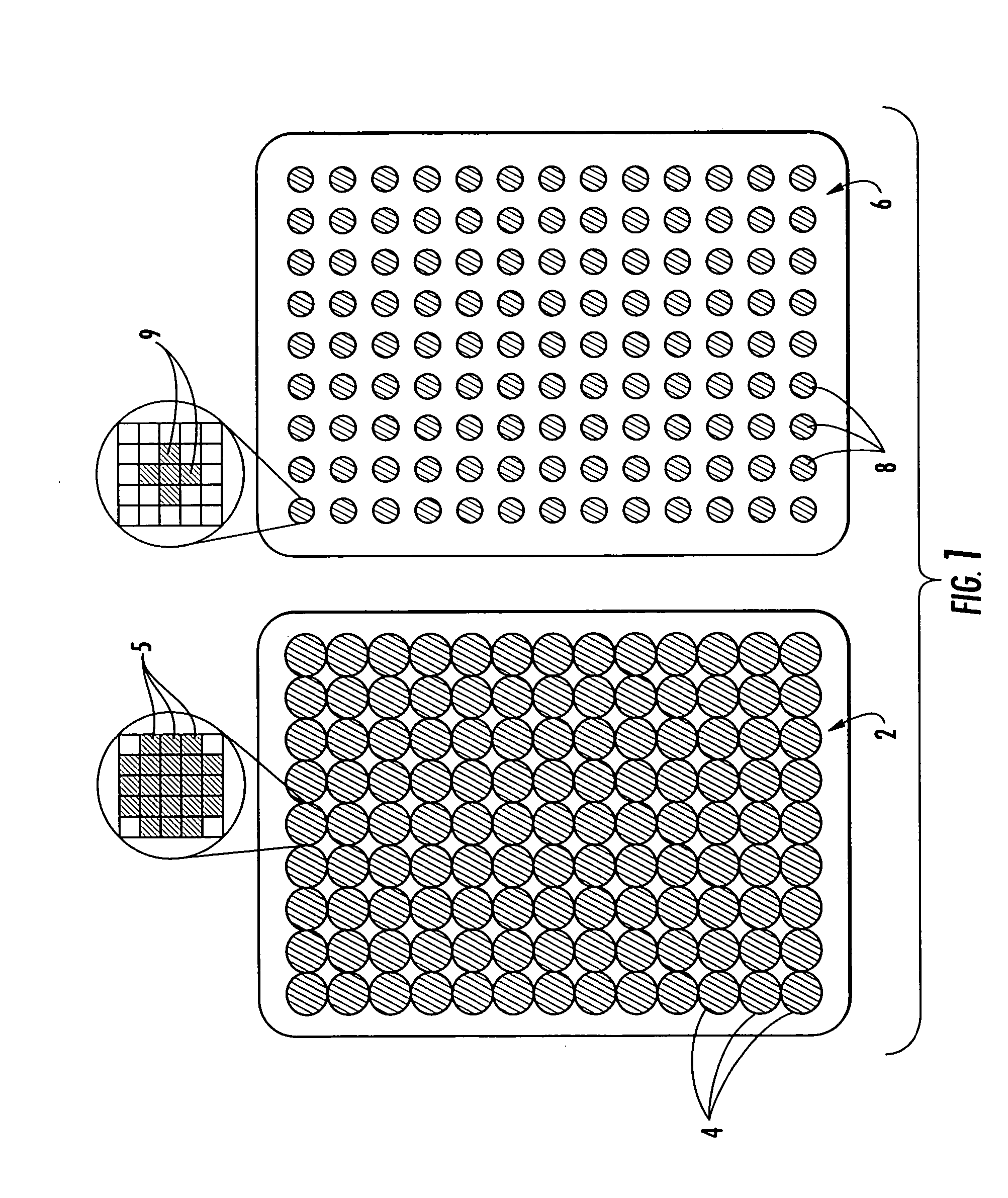
[0028] Now referring to the drawings, the state of the present art and the principals of the present invention are shown and generally illustrated in the figures. As was discussed earlier, the present invention is directed to a thermal printing apparatus and a method of controlling a thermal printing apparatus in a manner that maintains highly consistent print density and thus provides improved print quality. FIG. 1 illustrates the general principals associated with thermal printing technology. Thermal printers include a limited number of available color ribbons from which to generate a printed image. Generally, these ribbons include the following colors: cyan, magenta, yellow and occasionally black. To create varying shades of these colors, or to create other colors, the printer utilizes various combinations of the available colors in varying intensities in overlying relation. Further, since only one shade of each color is available for use in the printer, the printer utilizes a pr...


PUM


Abstract

A thermal printing apparatus and a method of controlling a thermal printing apparatus is provided wherein the duration of the strobe pulse utilized to transfer the ink from the carrier to the media is controlled and adjusted by a correction factor. The correction factor is calculated by the printer controller based directly on feedback regarding the actual transport time required to advance the media between encoder steps. Generally, the present invention controls a thermal printer in a manner that accounts for the transport speed between each encoder step and applies the correction factor to the strobe signal duration in a manner that maintains a uniform print density.

Description

BACKGROUND OF THE INVENTION [0001] The present invention relates generally to the area of thermal transfer printers. More specifically, the present invention relates to a thermal printer and a control process for thermal transfer printers that print on die-cut label media. [0002] In general, the technology related to direct thermal and thermal transfer printers is well known in the prior art. Thermal transfer printers are designed for printing onto non-sensitized materials such as paper or plastic films. In the printing process, a transfer ribbon that includes a heat-transferable ink layer deposited on one side thereof is interposed between the media to be printed and a thermal print head that includes a row of very small, tightly spaced heater elements. To affect the transfer of the ink from the transfer ribbon to the media, an electrical pulse is applied to a selected subset of the heater elements within the printer head, thereby melting and transferring the ink adjacent the heate...

Claims


Application Information

Patent Timeline
IPC IPC(8): B41J2/36
CPCB41J2/355B41J3/4075B41J11/42
Inventor MULHEARN, CHRISSHAW, JAMES E. III
Owner ASTRO MED
Why Eureka
Try Eureka