Projector and exposure adjustment method

a projector and exposure adjustment technology, applied in the field of projectors, can solve the problems of insufficient and inaccurate keystone correction, projector pj may still block the user's view, failure to accurately identify, etc., and achieve the effect of increasing the average of luminance values, increasing the luminance value difference, and accurate keystone correction

Inactive Publication Date: 2006-08-10
SEIKO EPSON CORP
View PDF18 Cites 47 Cited by
  • Summary
  • Abstract
  • Description
  • Claims
  • Application Information

AI Technical Summary

Benefits of technology

[0092] As described above, the target exposure setting table stored in the projector 100 sets the target exposure to ensure distinct identification of a peak position corresponding to each elevation angle. The CPU 120 refers to this target exposure setting table and sets the target value of exposure adjustment in the imaging control unit 105. The imaging control unit 105 adjusts the exposure to attain the set target exposure. The exposure adjustment gives a distinct peak position in a photographed image. This arrangement of the embodiment thus enables distinct identification of the position of maximum luminance and ensures adequate and accurate keystone correction.
[0093] The target exposure setting table has the greater target exposure corresponding to the larger elevation angle. In the inclined attitude of the projector 100 to have the larger elevat...

Problems solved by technology

On some occasions, even when the projection lens is shifted to the allowable limit of the lens shift, the projector PJ may still block the user's view.
In the state of elevation projection, the conventional technique may give only an i...

Method used


Image

  • Projector and exposure adjustment method
  • Projector and exposure adjustment method
  • Projector and exposure adjustment method

Examples


embodiment

A. Embodiment

A1. General Configuration of Projector

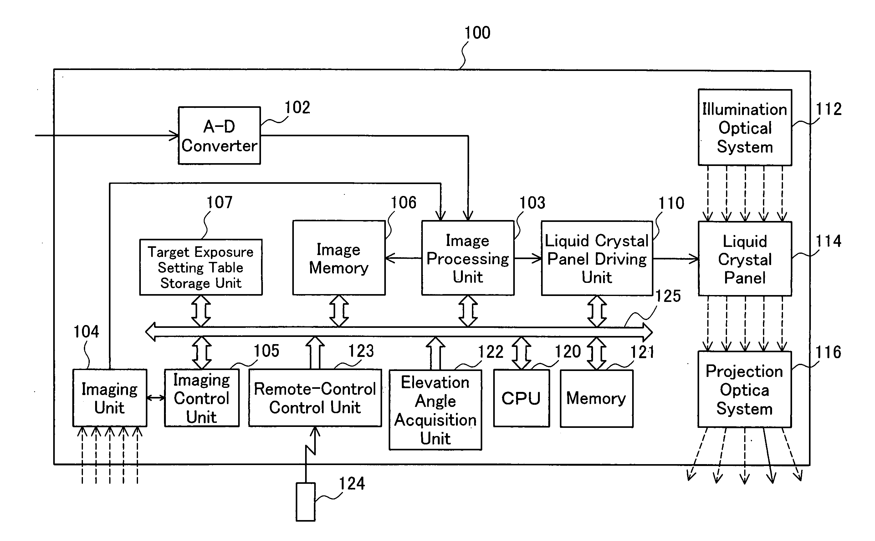
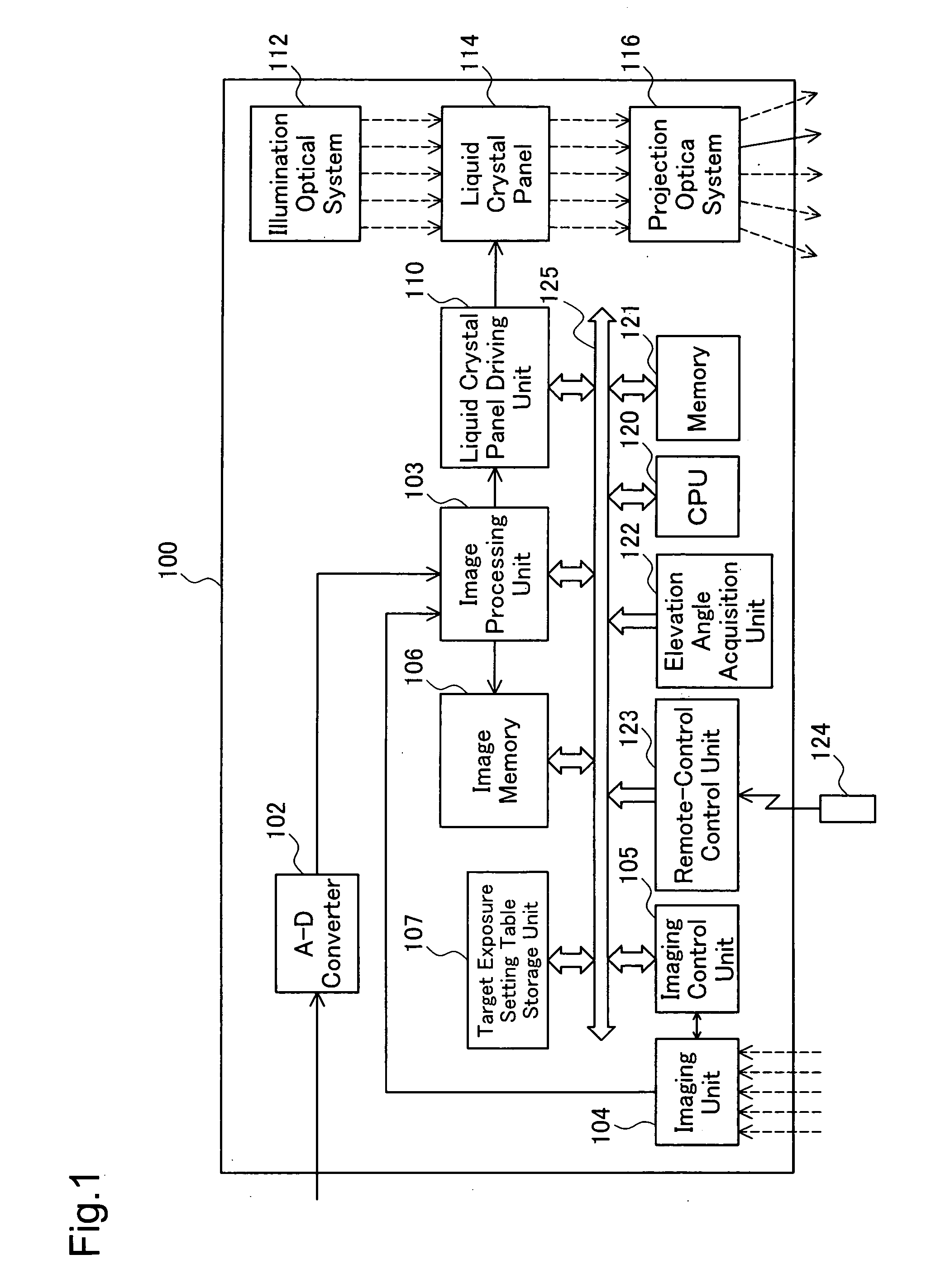
[0047]FIG. 1 schematically illustrates the configuration of a projector 100 in one embodiment of the invention. The projector 100 of this embodiment has the functions of photographing a projected image on a screen, identifying the position of maximum luminance in the photographed image, and making keystone correction, like the conventional projector PJ shown in FIGS. 5 through 7.

[0048] As illustrated, the projector 100 includes an A-D converter 102, an image processing unit 103, an imaging unit 104, an imaging control unit 105, an image memory 106, a target exposure setting table storage unit 107, a liquid crystal panel driving unit 110, a CPU 120, a memory 121, an elevation angle acquisition unit 122, a remote-control control unit 123, and a remote control 124.

[0049] The projector 100 also has optical elements, that is, an illumination optical system 112 including a lamp and a reflector (not shown), a liquid crystal panel 114, a...

modified example 1

B1. MODIFIED EXAMPLE 1

[0096] In the structure of the embodiment, the target exposure setting table is stored in the projector 100 before shipment. This is, however, not essential. In one possible modification, the user may directly connect a personal computer or an equivalent device to the projector 100 after shipment and store a target exposure setting table prepared by the user into the target exposure setting table storage unit 107.

[0097] Such modification enables the user to set the optimum target exposure for the actual working environment of the projector 100 (for example, for a projection object other than a screen).

modified example 2

B2. MODIFIED EXAMPLE 2

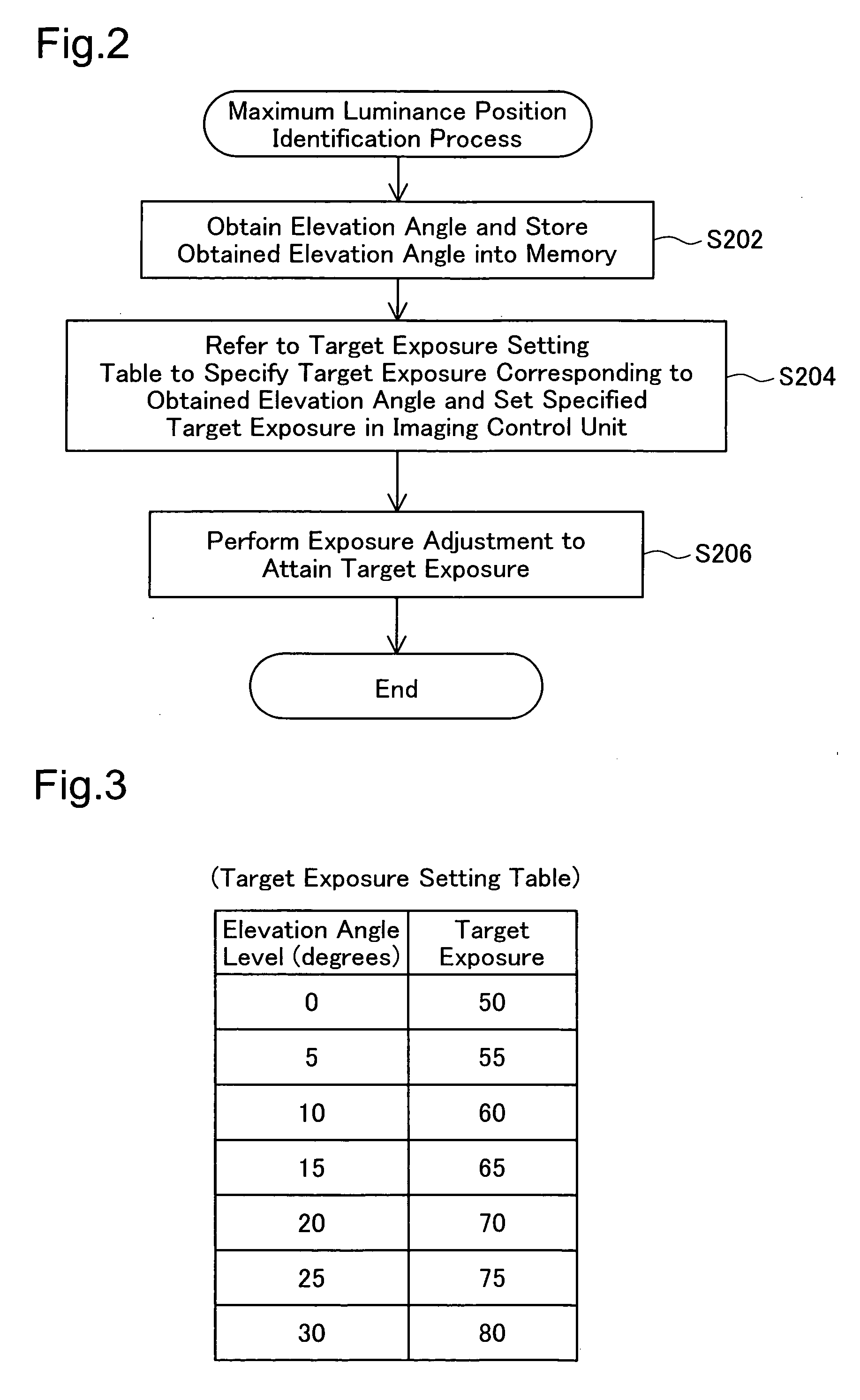
[0098] The target exposure setting table of the embodiment has the target exposures set corresponding to the elevation angle levels of 5-degree intervals as shown in FIG. 3. The interval of the elevation angle level in the target exposure setting table is, however, not restricted to the 5-degree interval but may be any larger or smaller interval than the 5-degree interval, for example, 4-degree interval or 6-degree interval.

[0099] The target exposure setting table of the embodiment may be replaced by a computational expression, which is experimentally or otherwise determined to compute the target exposure from the elevation angle as a parameter. In this modification, the CPU 120 computes the target exposure from the elevation angle obtained by the elevation angle acquisition unit 122 according to this computational expression and specifies the computed target exposure as the target value of exposure adjustment.


PUM


Abstract

A projector of the invention includes: an imaging structure that photographs an image projected on a projection object to take a photographed image; an imaging control module that performs exposure adjustment in the imaging structure to attain a preset target exposure; a control module that sets the target exposure in the imaging control module; an angle information acquisition module that obtains angle information representing an inclination of the projector to the projection object; and a storage unit that stores a map representing a variation in target exposure against the angle information. The control module controls the angle information acquisition module to obtain the angle information, refers to the map stored in the storage unit to specify a target exposure corresponding to the obtained angle information, and sets the specified target exposure in the imaging control module. Even in the state of elevation projection, this arrangement of the invention enables distinct identification of a maximum brightness position in the photographed image.

Description

BACKGROUND OF THE INVENTION [0001] 1. Field of the Invention [0002] The present invention relates to a projector that projects an image on a screen or another projection object and photographs the projected image. More specifically the invention pertains to a technique of accurately identifying the position of maximum brightness in the photographed image even in an inclined attitude of the projector to the projection object. [0003] 2. Description of the Related Art [0004] Various projectors have been proposed to photograph a projected image on a screen or another projection object with, for example, a CCD (Charge Coupled Device) camera and to adjust the zoom and the focus and correct a trapezoidal distortion of the projected image (keystone correction) based on the photographed image. [0005] One of such projectors is disclosed in Japanese Patent Laid-Open Gazette No. 2004-312690. This prior art projector analyzes a photographed image, identifies the position of maximum brightness in...

Claims


Application Information

Patent Timeline
IPC IPC(8): H04N5/228G03B21/00H04N5/74
CPCH04N9/3179H04N9/3194H04N9/3197
Inventor MIYASAKA, NORIAKI
Owner SEIKO EPSON CORP
Why Eureka
Try Eureka