
Apparatus and method for compensating for frequency offset in wireless communication system

a wireless communication system and frequency offset technology, applied in the direction of orthogonal multiplex, multiplex communication, digital transmission, etc., can solve the problems of complex signal processing algorithm, complex receiver implementation, and large influence of receiver performance on the transmission performance of the entire system

Inactive Publication Date: 2006-08-10
SAMSUNG ELECTRONICS CO LTD
View PDF14 Cites 84 Cited by
  • Summary
  • Abstract
  • Description
  • Claims
  • Application Information

AI Technical Summary

Benefits of technology

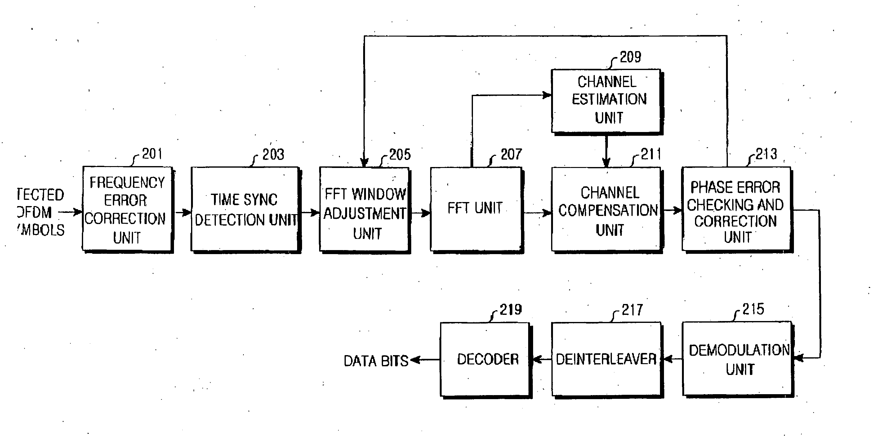
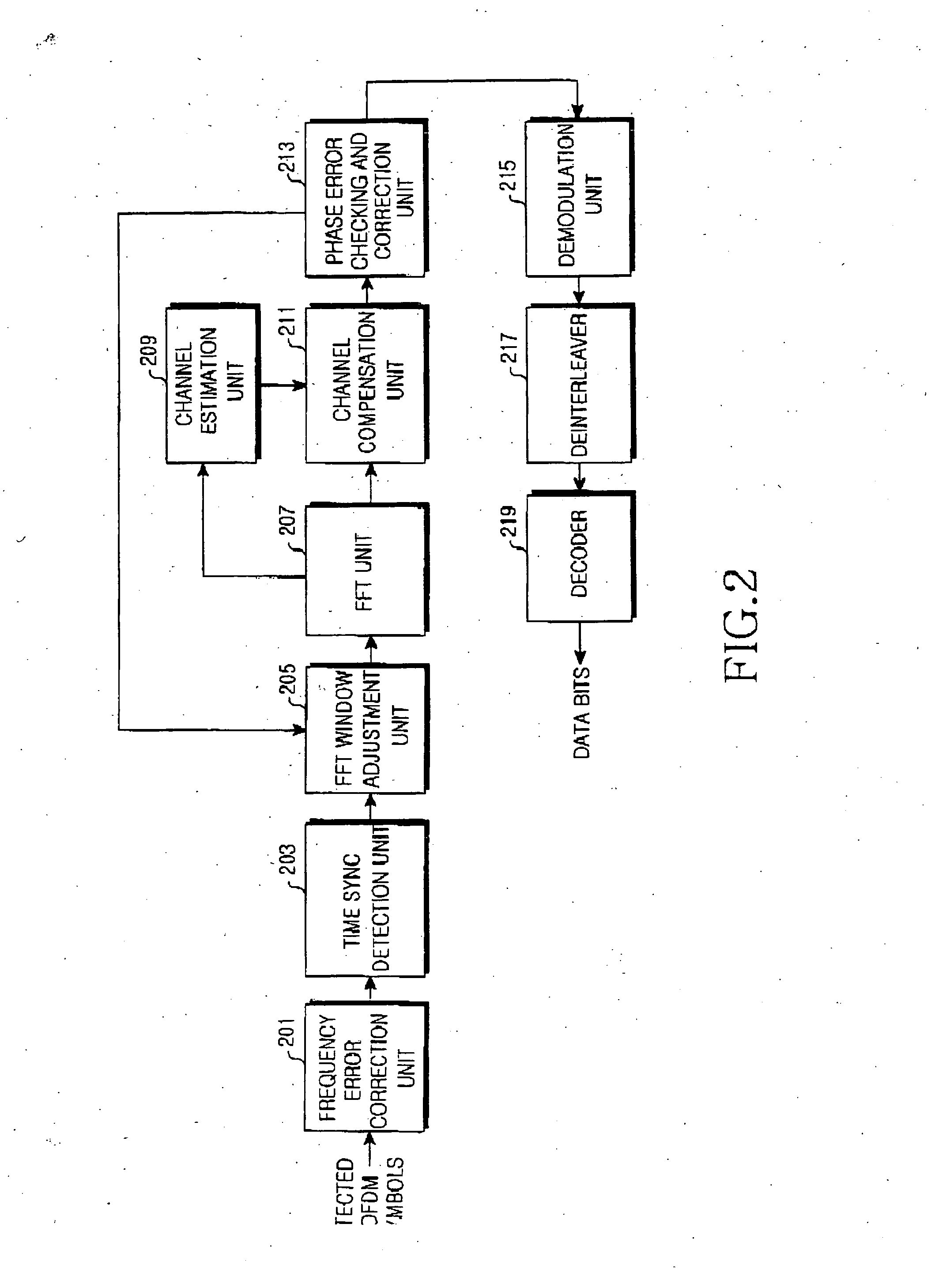
The present invention provides an apparatus and method to compensate for frequency offset, phase change, sampling frequency offset, and carrier frequency offset in a wireless communication system using an OFDM system. The apparatus includes an FFT window adjustment unit, an FFT unit, a channel estimation unit, a channel compensation unit, and a phase error tracking and correction unit. The method includes receiving sampling data, setting a start point of a first FFT window, transforming time-domain symbols into frequency-domain symbols, calculating FFT coefficients, estimating a channel state, compensating for frequency-domain symbols, detecting sampling frequency offset and phase change of a carrier signal, and compensating for phase distortion of a data signal. The technical effects of the present invention include improving the accuracy and reliability of wireless communication systems, reducing signal distortion, and improving data transmission quality.

Problems solved by technology

The implementation of the receiver is more complicated than that of the transmitter.
Accordingly, the performance of the receiver greatly affects the transmission performance of the entire system.
The receiver requires a complicated signal processing algorithm, which may differ from system to system, for restoring the signal distorted due to the wireless channel having the multipath characteristic and the incompleteness of analog components.
Although the performance of the receiver increases as the complexity of signal process is increased, the implementation of the receiver becomes complicated, so that the size of the semiconductor components and power consumption are increased.
In the above-described structure of the receiver, signal distortion that follows a transmission error may occur due to non-orthogonality among the orthogonal frequencies, i.e., subcarriers.
First is the case in which the receiver cannot accurately be synchronized with the carrier frequency produced in the transmitter.
Second is the case in which the sampling frequency used in a Digital-to-Analog Converter (DAC) of the transmitter is not accurately synchronized with the sampling frequency used in a DAC of the receiver.
Accordingly, if the phase change due to the carrier frequency offset and the phase change according to the increase of the subcarrier index cannot accurately be estimated and compensated for, i.e., if the frequency offset cannot accurately be compensated for, the receiver would be unable to restore the transmitted signal.

Method used


Image

  • Apparatus and method for compensating for frequency offset in wireless communication system
  • Apparatus and method for compensating for frequency offset in wireless communication system
  • Apparatus and method for compensating for frequency offset in wireless communication system

Examples


Embodiment Construction

[0035] Preferred embodiments of the present invention will be described in detail hereinafter with reference to the accompanying drawings. In the following description of the present invention, the same drawing reference numerals are used for the same elements even in different drawings. Additionally, a detailed description of known functions and configurations incorporated herein will be omitted when it may obscure the subject matter of the present invention.

[0036]FIG. 2 is a block diagram illustrating the internal construction of a receiver for compensating for frequency offset in an OFDM system according to a preferred embodiment of the present invention. Hereinafter, with reference to FIG. 2, the construction and operation of a receiver of an OFDM system according to the present invention will be explained in detail.

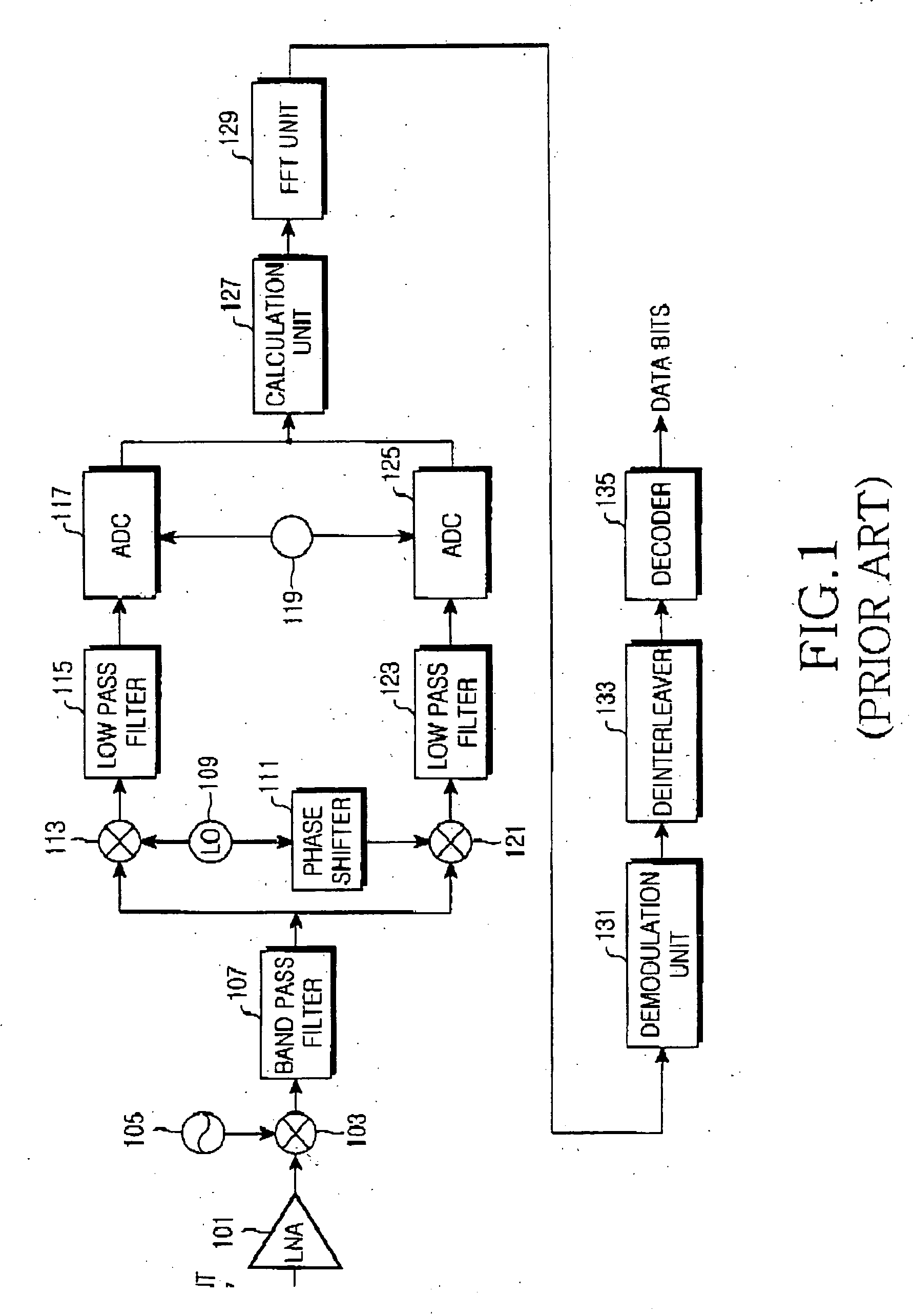
[0037] In FIG. 2, the wireless processing part that transforms the RF signal into the baseband signal as illustrated in FIG. 1 is not illustrated. Although a packe...


PUM

PropertyMeasurementUnit
carrier frequencyaaaaaaaaaa
frequencyaaaaaaaaaa
sampling frequenciesaaaaaaaaaa

Abstract

Disclosed is an apparatus and method for compensating for frequency offset in a wireless communication system using an OFDM system which can compensate for phase change due to carrier frequency offset and sampling frequency offset of data carried on subcarriers. The apparatus includes an FFT window adjustment unit for receiving sampling data when a packet is received, setting a start point of a FFT window at a start point of long training symbols and adjusting a position of the FFT window according to an input window adjustment value, an FFT unit for receiving an output of the FFT window adjustment unit, transforming time-domain symbols into frequency-domain symbols and calculating FFT coefficients, a channel estimation unit for receiving the coefficients from the FFT unit, estimating a channel state and outputting a value for compensating for an estimated value, a channel compensation unit for compensating for the frequency-domain symbols using the output of the channel estimation unit and a phase error tracking and correction unit for receiving an output of the channel compensation unit, detecting a sampling frequency offset and a phase change of a carrier signal and outputting the window adjustment value to the FFT window adjustment unit.

Description

PRIORITY [0001] This application claims priority to an application entitled “Apparatus and Method for Compensating for Frequency Offset in Wireless Communication System” filed in the Korean Industrial Property Office on Feb. 4, 2005, and assigned Serial No. 2005-10872, the contents of which are hereby incorporated by reference. BACKGROUND OF THE INVENTION [0002] 1. Field of the Invention [0003] The present invention relates to an apparatus and method for compensating for frequency offset in a wireless communication system, and more particularly to an apparatus and method for compensating for frequency offset in a wireless communication system that uses an Orthogonal Frequency Division Multiplexing (OFDM) system. [0004] 2. Description of the Related Art [0005] A wireless communication system transfers data using specified frequencies. Wireless communication systems have been classified into several kinds of wireless communication system. A representative wireless communication system...

Claims


Application Information

Patent Timeline
Patent Type & Authority Applications(United States)
IPC IPC(8): H04J11/00
CPCH04L27/2657H04L27/2665H04L27/2675H04L27/2695B32B5/022B32B7/12B32B21/042B32B21/10B32B21/14B32B2419/04E04F15/042
Inventor KO, SEONG-YUNYOUN, MYEON-KEEPARK, JOO-YONGSONG, HAK-HOON
Owner SAMSUNG ELECTRONICS CO LTD
Learn More