
Horizontal injection molding machine with turning device

a turning device and injection molding machine technology, applied in the direction of manufacturing tools, drawing profiling tools, food shaping, etc., can solve the problems of limiting the opening stroke of the mold platen, only limited in width and depth of the half-mold, etc., and achieve the effect of short cycle tim

Inactive Publication Date: 2006-08-10
KRAUSSMAFFEI TECH GMBH
View PDF10 Cites 39 Cited by
  • Summary
  • Abstract
  • Description
  • Claims
  • Application Information

AI Technical Summary

Benefits of technology

[0010] As the turning device is supported solely on the machine bed, the supply of media to the rotatably supported half-molds is additionally simplified. Cooling water, oil, air can be conducted through rotary feedthroughs, with the connection being located in the area of the machine bed, and cables for transmitting or tapping signals are also easy to implement. This can be appreciated in particular when using such injection molding machines with turning device in a clean room environment. As the moving parts of the turning device are movably supported only on the base plate situated underneath the molds and no further underpinning parts are required, the use of a continuous clean air flow box is possible to effect a laminar air stream above the machine to the machine bed so that rubbed-off particles or similar contaminants are prevented from contacting the produced injection-molded parts.
[0025] There is also the possibility to advantageously produce large-area single-component plastic parts with a horizontal injection molding machine according to the invention, with a carrier block carrying four or two identical half-molds which cooperate with two further half-molds secured to the moving mold platens. Thus, in each closing position of the injection molding machine, two identical parts can be produced, after opening the mold platens, the rotation direction is adjusted by 90°, and the mold platens are again brought into a closing position. While two further identical parts are made, the parts made in a preceding step are removed laterally between the tie bars of respective removal assemblies from the half-molds carrying them. In this mode of operation, the turning device may either be rotated further by 90° in each step, i.e. operated in rotary mode, whereby four identical half-molds must be situated on the carrier block. In the event, the carrier block carries two different types of half-molds in opposite relationship, the turning device indexes by 90° in reversible mode, i.e. per step two different parts are molded parallel, in the next step two different parts are again molded with the carrier block rotated by 90°, while the parts being produced in the preceding step can be removed laterally between the tie bars. In the following cycle, the turning device rotates back so that again two different parts can be produced whereas the previously produced ones are removed. In this mode of operation, a great number of plastic parts can be made in very short cycle time.

Problems solved by technology

The only limitation is to make sure that the half-molds do not touch the tie bars during rotation.
As long as they have a length dimension which is smaller than a vertical distance between the tie bars of the injection molding machine, the width and depth of the half-molds is only limited by the available space, when the mold platens are open, i.e. the opening stroke of the mold platens is the limiting factor.

Method used


Image

  • Horizontal injection molding machine with turning device
  • Horizontal injection molding machine with turning device
  • Horizontal injection molding machine with turning device

Examples


Embodiment Construction

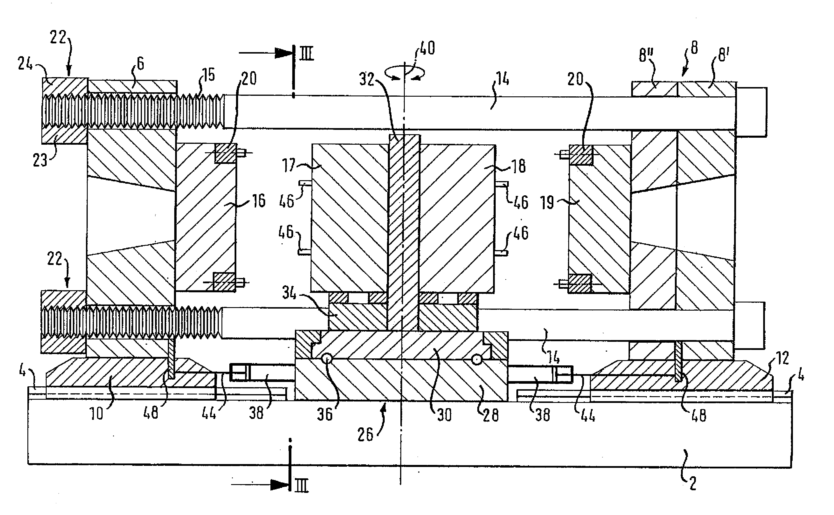
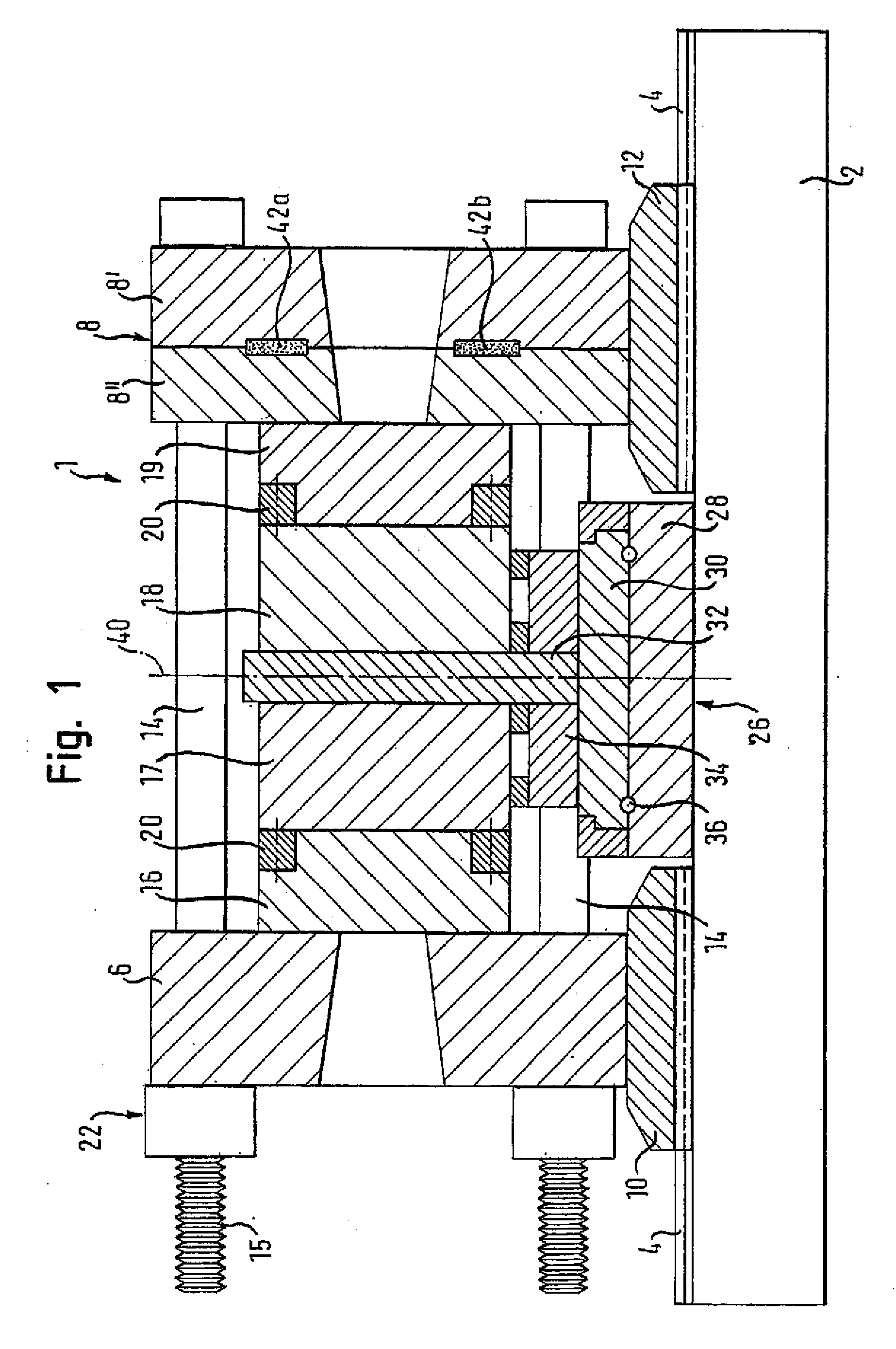
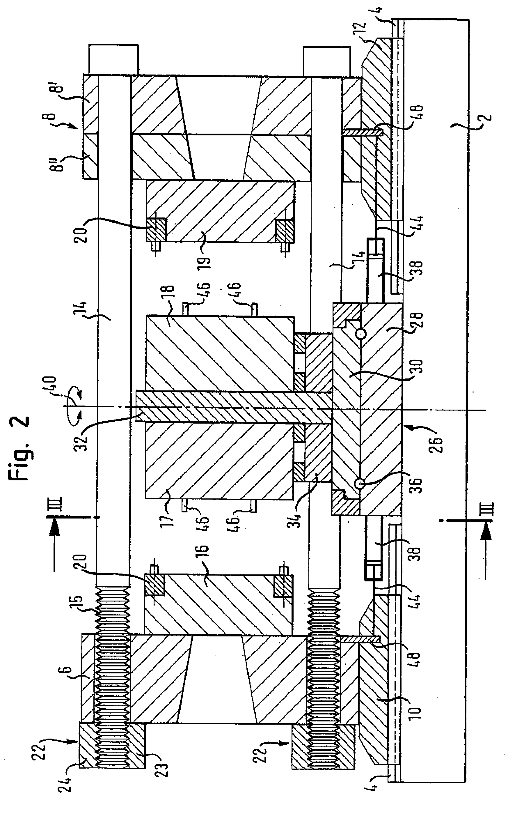
[0034] Throughout all the Figures, same or corresponding elements are generally indicated by same reference numerals. These depicted embodiments are to be understood as illustrative of the invention and not as limiting in any way. It should also be understood that the drawings are not necessarily to scale and that the embodiments are sometimes illustrated by graphic symbols, phantom lines, diagrammatic representations and fragmentary views. In certain instances, details which are not necessary for an understanding of the present invention or which render other details difficult to perceive may have been omitted.

[0035] Turning now to the drawing, and in particular to FIG. 1, there is shown a schematic longitudinal section of an injection molding machine according to the present invention, generally designated by reference numeral 1 and defining a longitudinal axis. The injection molding machine 1 has a machine bed 2 for support of two moving mold platens 6, 8 which have sliding shoe...


PUM

PropertyMeasurementUnit
Pressureaaaaaaaaaa
Areaaaaaaaaaaa
Heightaaaaaaaaaa

Abstract

A horizontal injection molding machine includes a machine bed defining a longitudinal axis and two mold platens supported on the machine bed for movement in a direction of the longitudinal axis, whereby each of the mold platens carries a half-mold. Further provided is a turning device which carries at least two half-molds for interaction with the half-molds on the mold platens, and includes a base plate, which is fixedly mounted to the machine bed between the mold platens, a turntable, and a bearing unit supporting the turntable on the base plate on one side for rotation about a vertical axis. The half-molds of the turning device are hereby attachable on a base-plate distal side of the turntable. The mold platens are moved by a drive mechanism in relation to the turning device, and tie bars extend between the mold platens and are constructed to resist a clamping force.

Description

CROSS-REFERENCES TO RELATED APPLICATIONS [0001] This application is a continuation of prior filed copending PCT International application no. PCTIEP2004 / 011237, filed Oct. 8, 2004, which designated the United States and on which priority is claimed under 35 U.S.C. §120, and which claims the priority of German Patent Application, Serial No. 103 47 638.5, filed Oct. 9, 2003, pursuant to 35 U.S.C. 119(a)-(d), the contents of which are incorporated herein by reference. BACKGROUND OF THE INVENTION [0002] The present invention relates, in general, to a horizontal injection molding machine with a turning device rotatable about a vertical axis for half-molds. [0003] A horizontal injection molding machine of this type is known, for example, from WO 03 / 013824 having a turning device provided for the half-molds and supported in a stationary frame which is mounted to a machine bed and traversed by the tie bars of the injection molding machine. This arrangement has the drawback that, on one hand...

Claims


Application Information

Patent Timeline
IPC IPC(8): B29C45/22B29C45/04B29C45/16B29C45/17
CPCB29C45/045B29C45/1628B29C45/1701B29C2045/1631
Inventor LICHTINGER, PETER
Owner KRAUSSMAFFEI TECH GMBH
Learn More