Actuator device

Inactive Publication Date: 2006-08-17
MITSUBA CORP
View PDF1 Cites 34 Cited by
  • Summary
  • Abstract
  • Description
  • Claims
  • Application Information

AI Technical Summary

Benefits of technology

[0030] As mentioned above, according to the first aspect of the invention, an elastic element supporting the motor in the motor housing unit in a floatable fashion is formed by a main body floating part for holding the motor main body of the motor and a pair of bearing floating parts for respectively holding the bearings in front and rear of the driving shaft of the motor and the main body floating part and the pair of bearing floating parts are integrally formed by way of an elastic element. This reduces the assembly man-hours and the overall cost as well as reliably supports the entire motor in a floatable fashion by using a simple structure. This reliably prevents malfunction or noise caused by deformation of a motor driving shaft or deviation of a motor.
[0031] According to the second aspect of the invention, a notch is formed between the main body floating part and at least one bearing floating part. It is thus possible to readily attach the main body floating part of the elastic element to the motor main body of the motor via the notch as well as readily attach the pair of beating floating parts of the elastic el

Problems solved by technology

Deformation or bending of the output of the motor 3 has sometimes resulted in poor engagement of the worm 4a of the output of the motor 3 with the deceleration

Method used


Image

  • Actuator device
  • Actuator device
  • Actuator device

Examples


Example

[0053] An embodiment of the invention will be described based on drawings.

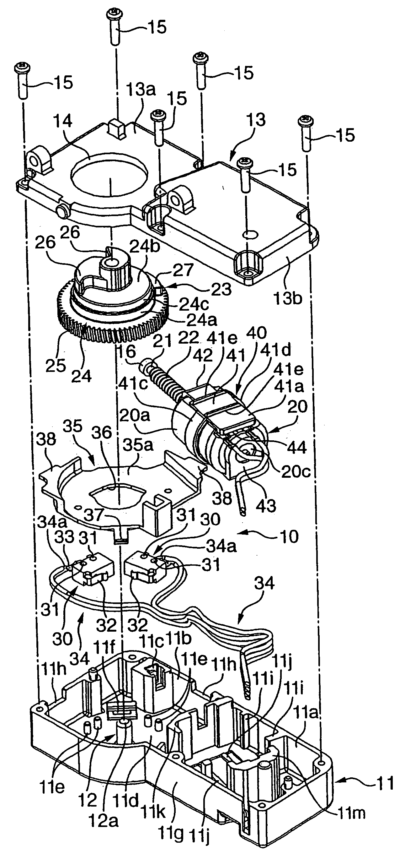
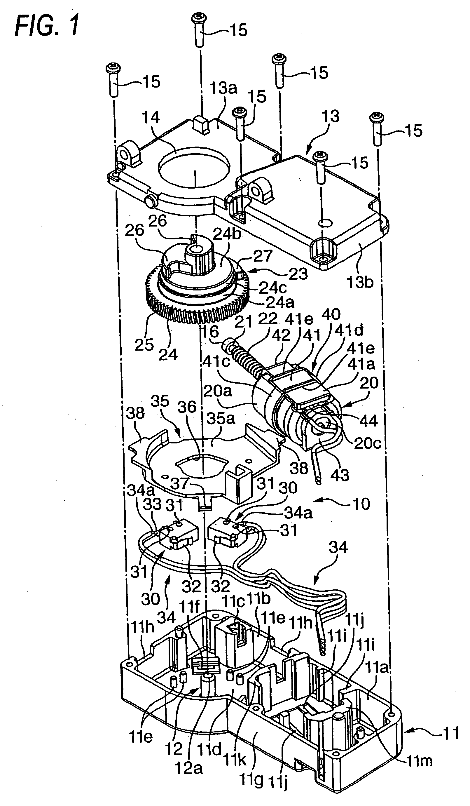
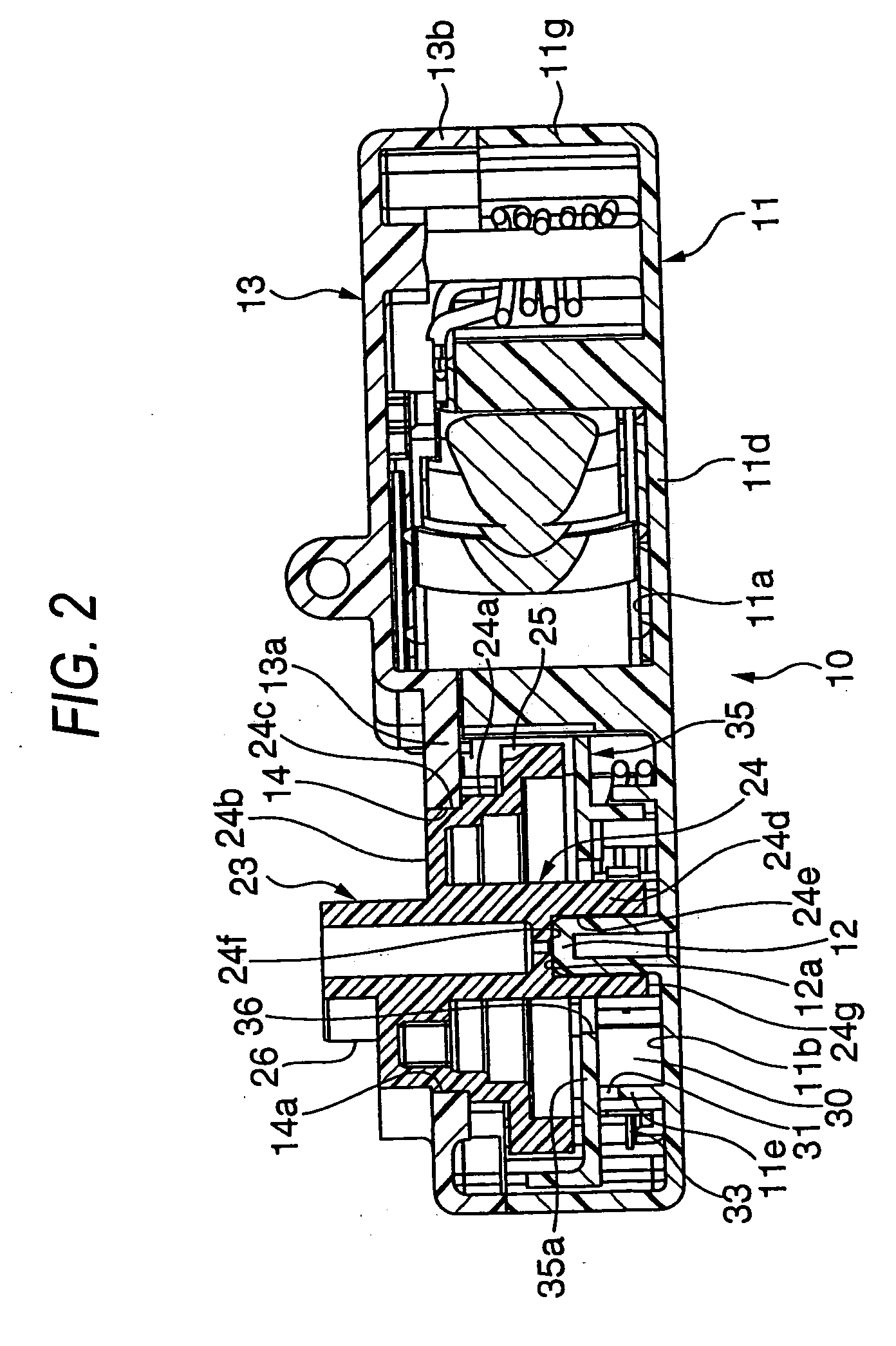
[0054]FIG. 1 is an exploded perspective view of a steering lock device according to an embodiment of the invention. FIG. 2 is a cross section of the steering lock device. FIG. 3 is a plan view of the case of the steering lock device. FIG. 4 is an enlarged plan view of the output gear of the steering lock device and its periphery. FIG. 5 is an enlarged cross section of the output gear and its periphery. FIG. 6 is an exploded perspective view showing the relationship between the case, a cover, a switch holder and a limit switch. FIG. 7 is a plan view showing a state where a switch holder is temporarily attached to the case. FIG. 8A is a cross section showing a state where a switch holder is temporarily attached to the case. FIG. 8B is an enlarged cross section of a main part with the switch holder temporarily attached. FIG. 9A is a general explanatory drawing of a mounting state where a switch holder is sandwic...


PUM


Abstract

The actuator device includes: a case having a motor housing unit and a gear housing unit; a motor housed in the motor housing unit; and an output gear rotatably housed in the gear housing unit of the case, the output gear driven to rotate by the driving shaft of the motor; the actuator device supporting the motor in a floatable fashion within the motor housing unit via an elastic element; characterized in that the elastic element includes a main body floating part for holding the motor main body of the motor and a pair of bearing floating parts for holding the bearings in front and rear of the driving shaft of the motor and that the main body floating part and the pair of bearing floating parts are integrally formed by way of an elastic element.

Description

BACKGROUND OF THE INVENTION [0001] The present application claims foreign priority based on Japanese Patent Application No.2005-37855 filed on Feb. 15, 2005, the content of which is incorporated herein by reference in its entirety, and concurrently with the filing of this patent application. [0002] The present invention relates to an actuator device preferably used for example in a steering lock device for locking / unlocking the steering shaft of a vehicle. [0003] A related art steering lock device incluldes: a case having a cover that covers a motor housing unit and a gear housing unit; a motor housed in the motor housing unit of the case; an output gear rotatably housed in the gear housing unit of the case, the output gear driven to rotate via a deceleration gear by the driving shaft of the motor; an output shaft penetrated by and fixed to the shaft of the output gear and rotating together with the output gear; an output cam part mounted on the output shaft for locking / unlocking th...

Claims


Application Information

Patent Timeline
IPC IPC(8): H02K5/24H02K7/10F16H57/02H02K7/116
CPCF16H57/021Y10T74/2186F16H2057/0213H02K7/1166
Inventor KAWAMOTO, MAKITOSHIMOYAMA, MASAYUKI
Owner MITSUBA CORP
Why Eureka
Try Eureka