Combined transformer and prefabricated substations

a transformer and prefabricated technology, applied in the direction of distribution substations, non-enclosed substations, substations, etc., can solve the problems of large radiation produced by transformers, inconvenient operation and maintenance of equipment, and poor auxiliary equipment, etc., to achieve high reliability, long service life, and great heat transfer capacity of heat pipes

Inactive Publication Date: 2006-08-17
ZENG QUINGGAN +2
View PDF1 Cites 23 Cited by
  • Summary
  • Abstract
  • Description
  • Claims
  • Application Information

AI Technical Summary

Benefits of technology

[0024] In above combined transformer and prefabricated substation, the heat transferring capacity of the heat pipe is great, and the substation has a long service life, a high reliability and occupies a small volume. The radiating effect has been greatly improved. Furthermore, the layout has been changed from the traditional layout so that the transformer chamber, LV chamber and HV chamber are arranged in a parallel and compact way in the same plane. The transformer chamber with large volume, the HV chamber with less operation and radiator at the bottom are set at the lower layer. The LV chamber with frequent operation, maintenance and high waterproof requirement as well as top radiator is set at the upper layer. In application, the lower layer is set underground, and with the upper layer above the ground, the occupied area has been

Problems solved by technology

If the combined transformer is completely buried underground, the equipment operation and maintenance will be inconvenient.
Also, it is not good for auxiliary equipment such as instruments which require waterproofing to be buried.
Furthermore, burying will cause problems for the large amount of radiation produced by the transformer.
If part of the installation is underground, the waterproof requirement for the HV chamber and the LV ch

Method used


Image

  • Combined transformer and prefabricated substations
  • Combined transformer and prefabricated substations
  • Combined transformer and prefabricated substations

Examples


Embodiment Construction

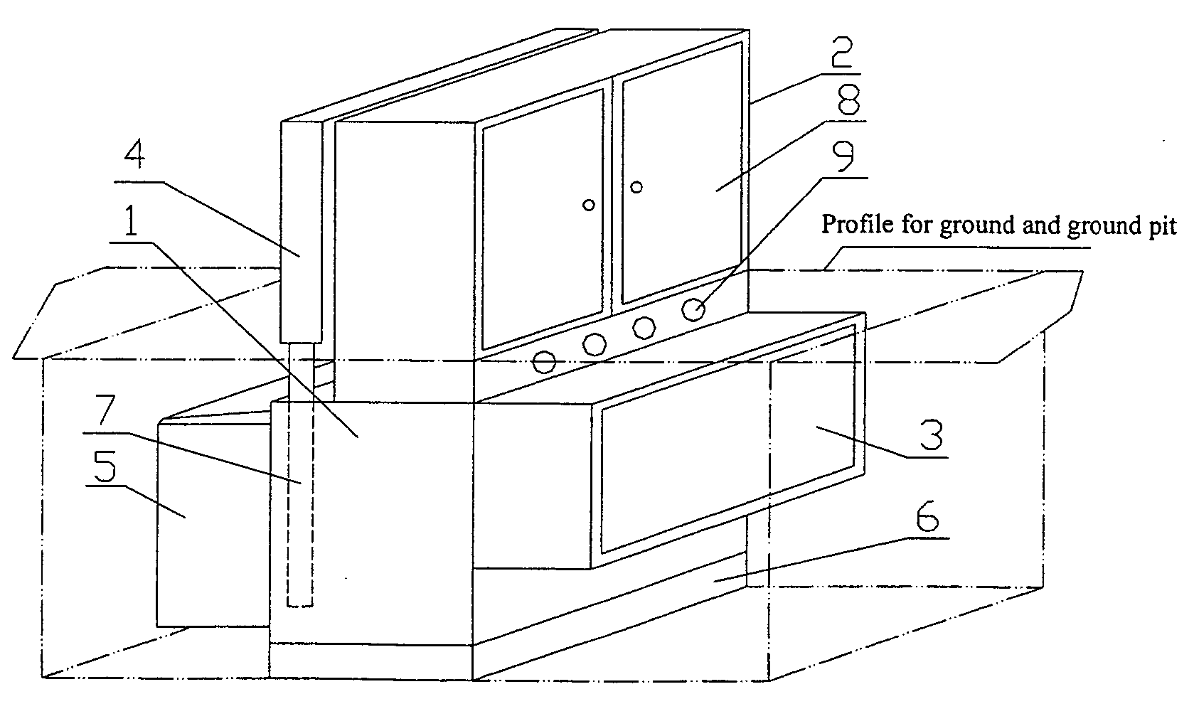
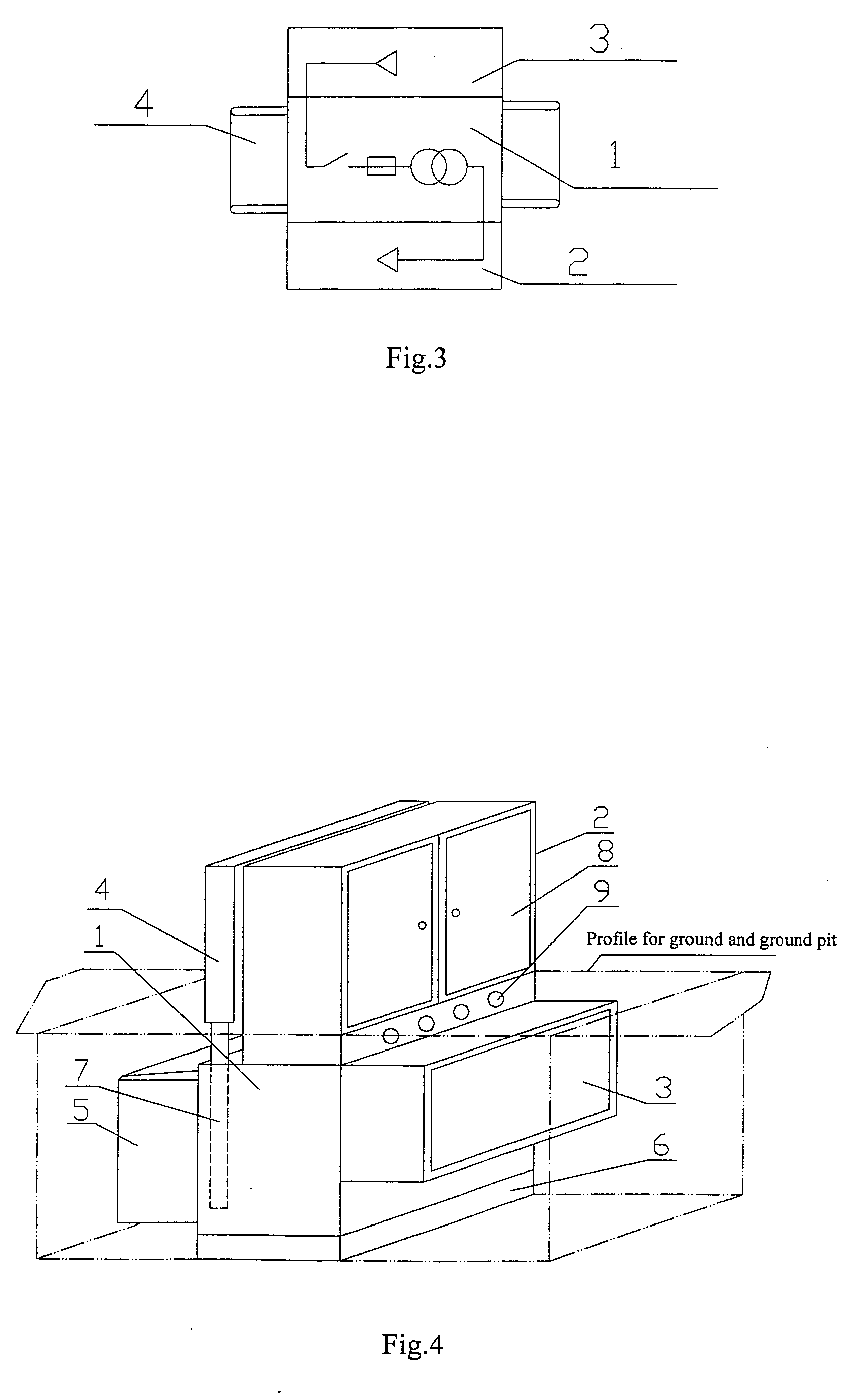
[0041] The following is the further description with two practical examples for the cubical type substation of the present invention. See reference drawings.

[0042] Combined Transformer

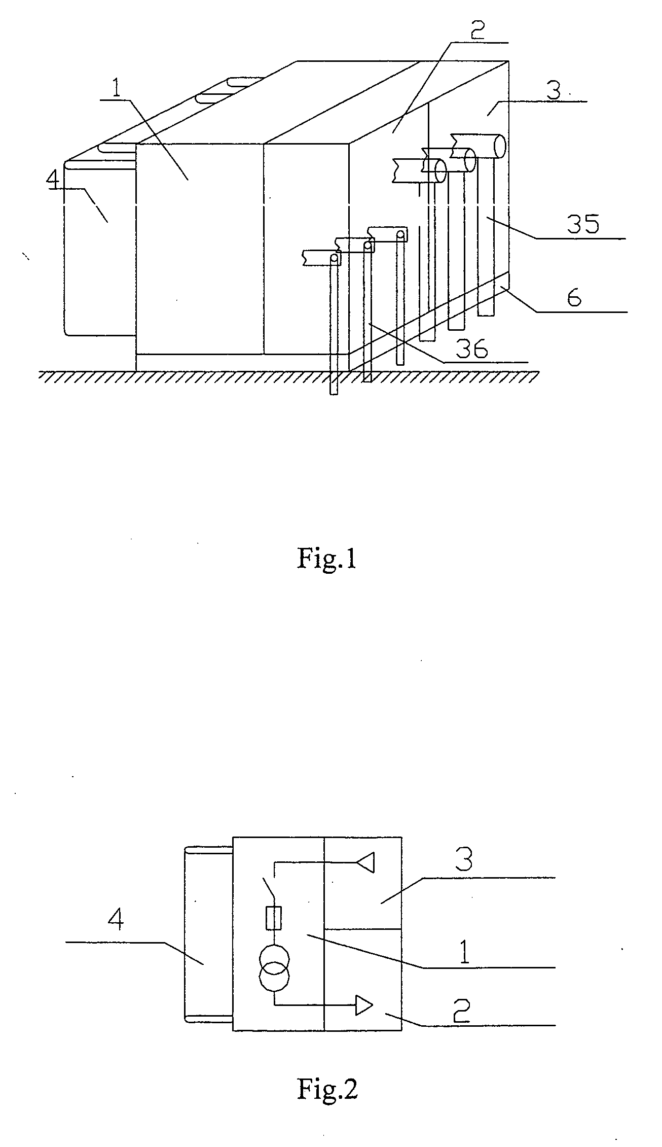
[0043] Referring to FIGS. 4-8, the combined transformer of the present invention includes transformer chamber 1, LV chamber 2, HV chamber 3, top radiator 4, bottom radiator 5, platform stand 6, transformer 13, transformer oil 14, protective fuse 15, HV load switch 16, tap switch 17, socket 24 for protective fuse 15, operating handle 25 for HV load switch 16, regulating handle 26 for tap switch 17, LV outgoing terminal 20, and HV cable socket 27.

[0044] The top radiator 4 is set above the transformer chamber 1 (FIG. 4). In addition, a split-type structure can also be adopted for the top radiator 4 and transformer chamber 1 (FIG. 5). The top radiator 4 includes heat pipes 7 and radiating fins 10. Many arrangement styles are available for the top radiator 4. The Heat pipes 7 and radiating fins 10 can be...


PUM


Abstract

A combined transformer is comprised of a transformer chamber, a low-voltage chamber, a high-voltage chamber and a radiator. There is a hollow thermal pipe filled with a heat-transfer medium in the radiator. One of the ends of the thermal pipe is plugged into the transformer chamber and on being located the other end there are heat sinks. Wherein the low-voltage chamber being located on the transformer and the high-voltage chamber being on the side of the transformer, the transformer chamber and the high-voltage chamber are embedded in the ground. The prefabricated substations are comprised of a transformer chamber, a transformer arranged in the transformer chamber, a switch chamber including a low-voltage chamber and a high-voltage chamber, a radiator and a hollow thermal pipe filled with a heat-transfer medium in the radiator. One of the ends of the thermal pipe is plugged into the transformer chamber and the other end is arranged thermally-conductive sheets, the thermally conductive sheets are located on the outside of the switch chamber which is arranged on the transformer chamber. The high-voltage chamber and the low-voltage chamber both have doors the transformer chamber is enclosed with a pit and a cover. The said thermal pipe of the transformer dose not only has the large capacity, the long using life and high reliability, small size and the heat-transfer effect greatly improved but greatly reduces the occupation area of the transformer.

Description

TECHNICAL FIELD [0001] This invention relates to cubicle type substations and especially to combined transformer and prefabricated substations. BACKGROUND OF THE INVENTION [0002] Cubicle type substations are widely used in the power transmission and distribution industry and include combined transformer and prefabricated substations. The introduction is as follows: [0003] Combined Transformer [0004] Combined transformer is a term used in China Machinery Industry Standard JB / T 10217-2000 “Combined Transformer.” Since the technology of this product comes from U.S.A., the combined transformer is also called “American Cubicle Transformer.”[0005] In American National Standard ANSI / IEEE C57.12.26, combined transformers are called “three Phases Compartment-Type Pad-Mounted Transformers.” In the above standard, in Chinese patents such as “New type of combined transformer” (Patent No. 00217238.0), and in the product catalogs of American GE company and Shanghai Zhixin Company, the typical str...

Claims


Application Information

Patent Timeline
IPC IPC(8): H02B5/00H01F27/06H02B7/06
CPCH01F27/06H02B7/06
Inventor SUN, BINGZHENG, SHAOJUNLIU, AIHE
Owner ZENG QUINGGAN
Why Eureka
Try Eureka