Multi-stage amplifiers to reduce pop noise

Active Publication Date: 2006-08-17
TEXAS INSTR INC
View PDF14 Cites 20 Cited by
  • Summary
  • Abstract
  • Description
  • Claims
  • Application Information

AI Technical Summary

Benefits of technology

[0015] The present invention effectively prevents popping noises due to power-up of the amplifying circuitry, without using an external filter. Therefore, the amplifier can be completely integrated on an integrated circuit.

Problems solved by technology

Audio circuitry often suffers from annoying “pop” noises as power is applied to or removed from the audio amplification circuitry.
While the popping can be annoying in any application, it is particularly annoying in headset applications, where the speaker is firing directly into the user's ear.
In conjunction with mobile processing devices, power consumption is an especially important consideration, and power may be frequently switched on and off to the headset amplifier.
This solution has several problems.
Second, the settling time during the power-up, which depends on the R1C1 filter settling time, can be excessive.
Third, the discharge phase is lengthy and may not meet timing constraints in certain applications.
While the cost of the capacitor 22 and extra pin is small for a single device, given the large number of devices generally produced, the overall cost can be significant to the manufacturer.

Method used


Image

  • Multi-stage amplifiers to reduce pop noise
  • Multi-stage amplifiers to reduce pop noise
  • Multi-stage amplifiers to reduce pop noise

Examples


Embodiment Construction

[0029] The present invention is best understood in relation to FIGS. 1-9 of the drawings, like numerals being used for like elements of the various drawings.

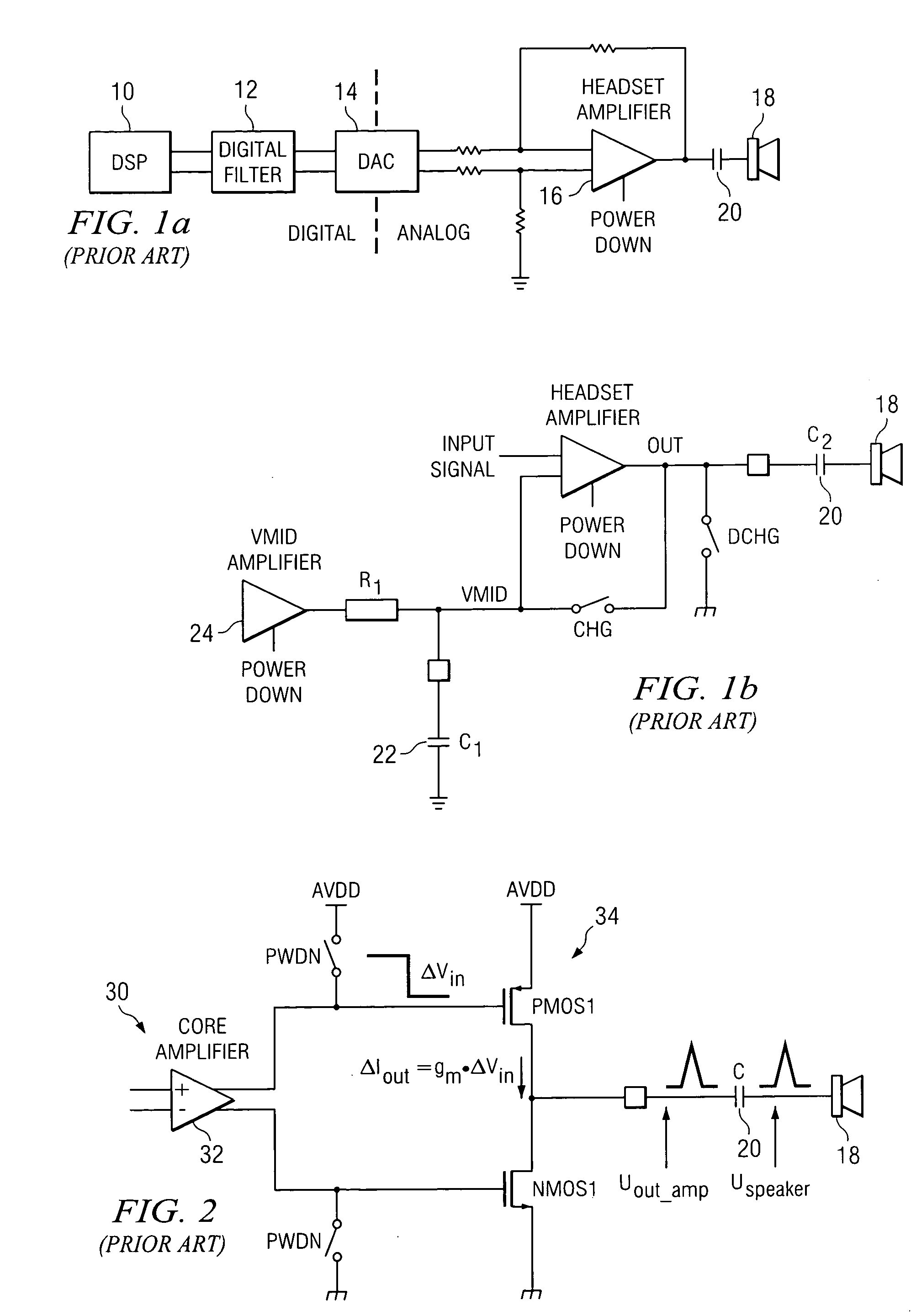
[0030]FIG. 2 illustrates a schematic representation of a typical voice or audio output amplifier 30. Amplifier 30 includes a core amplifier 32 and an output stage 34, which includes p-channel transistor PMOS1 and n-channel transistor NMOS1. PMOS1 and NMOS1 are driven by the outputs of core amplifier 32. The power-up and power-down phases are controlled by control signal PWDN, which implies a voltage step ΔVin on the gate of the transistor PMOS1 (and on the gate of NMOS1, assuming that the voltage step ΔVin has the same amplitude and opposite sign, for the PMOS and NMOS side).

[0031] The following description of the operation of the amplifier 30 applies to both the PMOS1 and NMOS1 sides of the output stage 32; for simplicity, only the PMOS1 side is described in detail.

[0032] The output transistor PMOS1 works as a transconductan...


PUM


Abstract

An amplifier (50) for voice or audio signals, and particularly for headset applications, uses a low gm amplifier (54) for initially charging an output node (OUT) at the beginning of a power-on phase. After charging the output node, a main amplifier (56) is enabled to amplify the voice or audio signal. At power-down, a sample-and-hold circuit (58) drives an output transistor to discharge an AC coupling capacitor (20). Thus, spikes at the output node are eliminated and an external filtering capacitor is not needed.

Description

CROSS-REFERENCE TO RELATED APPLICATIONS [0001] Not Applicable STATEMENT OF FEDERALLY SPONSORED RESEARCH OR DEVELOPMENT [0002] Not Applicable BACKGROUND OF THE INVENTION [0003] 1. Technical Field [0004] This invention relates in general to audio amplifiers and, more particularly, to a track-and-hold circuit to reduce noise in a headset amplifier. [0005] 2. Description of the Related Art [0006] Audio circuitry often suffers from annoying “pop” noises as power is applied to or removed from the audio amplification circuitry. While the popping can be annoying in any application, it is particularly annoying in headset applications, where the speaker is firing directly into the user's ear. [0007] Headsets are becoming more and more popular with mobile processing devices, and especially in communications applications, such as with mobile telephones (including devices such as personal digital assistants that may be used as a telephone, either through cellular circuitry or as a voice-over-Int...

Claims


Application Information

Patent Timeline
IPC IPC(8): H04M9/00
CPCH03F1/305H03F2203/7231H03F2203/7227H03F3/72H03F3/3022
Inventor SORACE, CHRISTIANCUSINATO, PAOLOKUBELEC, FREDERIC
Owner TEXAS INSTR INC
Why Eureka
Try Eureka